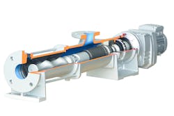
A progressing cavity pump has no suction or pressure valves. In other words, it has the outstanding self-priming characteristics of a piston pump. Moreover, it can promote any kind of inhomogeneous and abrasive media, even mixed with solid or fibrous matter, the same as a diaphragm or peristaltic pump.
Multiphase mixtures are also moved safely and gently by the progressing cavity pump. High viscosities are handled comparable to a gear or screw pump. The pump’s speed-dependent, continuous flow fulfills dosing tasks like a piston, diaphragm, gear or screw pump. In fact, the progressing cavity pump is found in all industrial areas where specific conveyance tasks are solved (see Table 1).
Progressing cavity pumps convey a variety of media but are used in particular for viscous, highly viscous and abrasive media, such as slurries, manure, mineral oil and fats (see Table 2).
Table 2. Types of media conveyed by progressing cavity pumps
Principle of operation
A progressing cavity pump is a kind of rotary positive displacement pump.
The main components are a rotating part, known as the rotor, and a stationary part, called the stator. The rotor is a kind of round thread screw with extremely high pitch, large thread depth and small core diameter. The elastic stator has a thread twice the pitch length of the rotor. This leaves conveying chambers between the stator and the rotor, which rotates within the stator radially. The conveying spaces move continuously from the inlet to the outlet side. Valves are not required to limit the conveying chambers.
The size of the conveying chambers and the pump’s theoretical output depends on the pump size. A 360-degree rotation at free discharge determines a volumetric flow rate per revolution. Pump flow rate varies by speed. The actual flow rate depends on the self-adjusting counter pressure. For example, if one of the maximum permissible pressure levels is set to 6 bar, and 12-stage conveyor elements are used, pressures up to 72 bar can be overcome.
The media strive for equalization, and because the seal between rotor and stator is not static, media will always flow from the pressure to the suction side. These slip-losses are reflected in a characteristics curve as the difference between the theoretical and actual flow rate.
The shape of the cavities is constant, so that the pumped media is not compressed. Not only fluids but also solids can be conveyed by a suitable progressing cavity pump. Shear forces acting on the material being conveyed are small. For example, whole fruits can be pumped. A particular advantage is that progressing cavity pumps have continuous flow with low pulsation. This makes them suitable for use in the casting industry.
Gentle conveying with low pulsation means suitable media ranges from water to media that no longer flows by itself. Because the flow rate is proportional to the speed, the progressing cavity pump can be used well in combination with corresponding measurement and control technology for dosing tasks.
Geometrics and other characteristics
Flow rate and its influence on any shear depends on the geometry of the processed stators. Usually, manufacturers offer different geometries. Caution should be exercised at the lowest offers in which L geometries are used. Although these can convey large amounts, they are not as resistant to pressure.
Elastomers are resistant to deformation but are elastically deformable plastics, whereas the glass transition point is below the operating temperature. The plastics can deform elastically in tension and pressure, but then return to their original, pre-deformation shape. These plastics are used for the inner layer of the stators. Different applications require different elastomers. In the sewage and biogas industries usually nitrile rubber is used. This material is good at high temperatures and resistant to abrasive materials.
Typically, bolt joints are used. The pump rotor is connected to the drive with a rod and a bolt. This is cost-effective, but it often leads to wear and tear on the load transmission point. A not-so-common but significantly more powerful joint is the Cardan joint, developed for the military. Wear and tear on this joint, also known as the universal or "U-joint," is virtually impossible due to encapsulation and size, so blockages by fibers are eliminated.
Transmissions
In connection with heavy, highly viscous media, the eccentric movements require a lot from the axis mounting. Again, varieties may differ from manufacturer to manufacturer.
Block pumps are coupled directly without their own bearings. This cuts the cost of ball bearings and requires little development work. However, most of the axial and radial forces are directed to the transmission, necessitating investment in a powerful transmission. Even then, gear damage is not uncommon during the operational phase.
A bearing frame pump with coupling captures the axial and radial forces from its own ball bearings, reducing the subsequent costs in gear area to near zero. However, coupling adjustment is relatively complicated and performed intermittently. Further, the structural design requires including a base plate for adjusting the rotational axes, which leads to significant overhead expenses.
A bearing frame pump with a direct flange mounting combines the advantages of the two previous solutions. Bearings mitigate the axial and radial forces, yet the disadvantages of a coupling solution do not apply.
While an additional expenditure for the block design ball bearing still exists, it eliminates the amplification of the transmission. Coupling, alignment and base plate are omitted in the construction.
Pumping biogas
The described properties of progressing cavity pumps make them the ideal pump for biogas plants.
In a biogas plant, suppliers of energy in the form of food waste, silage, recirculated material, pulp, manure and other items use a fermentation process to produce gases, which are then applied as more usable forms of energy. Pumps are required for various tasks:
- Substrate transfer between the fermenters with different viscosities
- Loading separators for separating the solid and liquid phases
- Adding fermentation substrates
- Conveying high-viscosity liquids from tanks and containers
The production of biogas begins with feeding substrates into a fermenter. Knowing the optimum mixture of liquid and solids, the amount of dry matter and the viscosity is crucial for selecting the right pump, and equally important for attaining an optimum energy yield.
In the assumed case, a substrate with 35 percent dry substance feeds into the fermenter. Added recirculates improve flow, dropping dry substance down to 8 percent. To make the substrate capable of flowing, a partial substance of at least two parts of recirculates needs to be added.
In other words, 35 percent + 8 percent + 8 percent = 51 percent /3 parts = 17 percent dry substance.
In addition, the bacteria digestion is more successful if the lumpiness is small. The finer the substrate, the better the mixing with liquid is and the energy is output.
Intelligent controls regulate the feeding of liquid prior to the fermenter and mix substrate with liquid optimally. The feeding methods have no limits. Push floors, attachments, feed conveyors and others transport the substrates typically with hopper pumps and feed screws. In some cases, prior to the feeding process, the substrate is already mixed using recirculates.
However, dry substance content is not the sole indicator of viscosity. Crude oil has a dry substance content of 99.99 percent but pumps easily. It is not so with hand creams, quark and yogurt, even though they have a dry substance content of only about 4 percent.
A dry substance content of 30 percent is generally already watertight, and usable levels extend from 5 percent to 18 percent in the scenarios under discussion.
Maintenance concerns
Solid substrates can contain foreign objects, such as stones, and hoppers with maintenance hatches allow foreign objects falling out of the substrate to be easily removed.
One disadvantage of progressive cavity pumps is that in case of service in rotor/stator changes, the pump must be disassembled forward/in the front. As a rule, the pump needs as much space as the rotor/stator unit is long. Quick-change systems assist to make handling easier.
Service friendly pumps are appropriate for heavy use. For example, it is an advantage if technicians do not have to remove the piping in the length of the rotor-stator unit. Maintenance is more likely performed in place. A disadvantage with such systems is that pressure stability is usually not equivalent to that of standard progressing cavity pumps.
Eduard Weiss is senior vice president at Wangen America Inc., part of the German Pumpenfabrik Wangen GmbH. Wangen has produced positive displacement pumps, such as progressing cavity pumps, since 1969 and specializes in biogas and heavy duty applications. For more information visit wangen.com/us.


