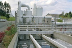
In the demanding environment of wastewater treatment, operators do not have time for devices that require constant maintenance and attention — there’s enough to do in a day without tending to temperamental instruments. At each stage of operation, the plant depends on reliable and accurate level measurement.
Walking through a treatment facility, level instrumentation is at work everywhere:
• In chemical storage tanks, ensuring process chemicals don’t run out or spill over the tanks that contain them.
• At the headworks, taking level measurements from a flume or weir to calculate volumes of effluent first entering the plant.
• In primary clarifiers, secondary clarifiers, sludge wells, filter beds and chemical tanks, controlling and monitoring levels.
Most of these level measurements are usually carried out using ultrasonic level controllers and transmitters. Occasionally, a plant might use radar transmitters due to the process connection limitations of a tank, chemical compatibility of the media or if the measurement range requires it.
However, contacting level technology such as guided wave radar is seldom used — and when it is, finds itself mostly in ammonia-level applications due to the aggressive nature of such media. The molecular makeup of ammonia tends to degrade some materials at a rapid pace. Luckily, some guided wave radar transmitters feature special seals that are well-suited for ammonia level applications. In such applications, this technology is the right choice.
Guided wave radar in a filter bed
A large wastewater treatment plant in North Carolina and its use of guided wave radar on a number of filter beds is provided here as an example.
Among the level applications previously mentioned, monitoring the water level in a filter bed is quite easy — and guided wave radar is rarely used. Most filter beds have accessibility to install level instruments, and their rectangular-shaped basins are usually free of obstructions that otherwise would interfere with an instrument’s signal reaching down to the lowest point.
A couple years ago, this wastewater treatment plant underwent a nearly 20-million-gallon-per-day expansion to meet growth demands in the area it served. The expansion included the design of fast sand filter beds using wash-water troughs and compressed air.
The large diameter wash-water troughs are spaced several feet apart; however, the influent trough pipe located above and between the wash-water troughs leaves only a 2-foot gap between them. This narrow gap between the large pipe and troughs prompted the use of guided wave radar level transmitters with flexible cables as the sensing elements.
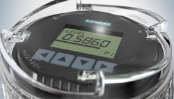
Figure 2. For manual observations, operators no longer need to remove the device’s lid, but instead can observe the values they need with ease.
Buildup trouble
During the washdown cycle, the water level is near the bottom of the basin and the water surface is turbulent. Operators were concerned that noncontacting technology would struggle to send its signal through free space as it attempted to detect the level past the exposed troughs.
Considering the narrow area available for level measurement in this application, guided wave radar technology seemed to be the right choice.
In the control room, the historical trend graphs showed that, for the most part, these devices tracked the level steadily during normal operation and backwash cycles. However, the graphs also showed periods of intermittent high-level indication — some of the spikes lasting a short time and others lasting several minutes.
At the filter beds, organic material was accumulating on most of the guided wave radar transmitters’ cables. This material was not uniformly spread out along the cable, and the amount of this organic buildup also varied.
Although newer versions of guided wave radar transmitters can automatically suppress buildup, filter beds in an open environment are exposed to changing weather, insects and anything else floating on the water surface or through the air.
Once debris begins to build up on cables or rods, moisture can more easily accumulate, and buildup will continue to grow. The greater the moisture content on the buildup, the more conductive this buildup becomes.
To the transmitter, this accumulated material begins to appear as a real target, which eventually leads to inconsistent level measurements. Automatic suppression of this buildup is not enough to overcome this challenge — not only because of the dynamics of the buildup, but also because the end of the transmitter’s cable must be completely unsubmerged for its automatic activation.
Operators did not immediately make the correlation between the intermittent high-level spikes and material sticking on the cables. They would occasionally spray the cables with high-pressure water jets during the periodic washdowns to keep the basin and surrounding area clean.
After washdown and once residual water was cleared off the cables, the operation of the guided wave radar devices improved — that is, until buildup started to return, thereby causing inference again.
Figure 3. Echo processing algorithms ensure reliable level readings. Accurate features include auto-false echo suppression.
A more permanent fix
Filter beds are an easy level measurement for transmitters using noncontacting ultrasonic technology. As the name implies, to obtain a level measurement with this technology, the sensor does not contact the liquid or solid’s surface. Instead, the measurement is derived using the time of flight principle: The echo signal generated by the instrument is transmitted and received by the transducer and the corresponding distance or level can be viewed on the device’s local display.
Most commonly, the 4-20 mA output signal is sent to the control room where it is relayed to a human machine interface (HMI). With the environmental industry’s ever-increasing digitalization efforts, level information can be interconnected with Siemens MindSphere for data analysis, better efficiency and process management.
With noncontacting technology, the issue with buildup developing on the area of transmission is nonexistent. Furthermore, the mechanical action generated by the piezoelectric crystals used to generate the echo pulse means that ultrasonic devices have self-cleaning faces, literally shaking themselves clean of dirt, condensation and buildup in the application. This minimizes the negative effects of condensation that otherwise would degrade the transmitted and received echo signals.
By using a transmitter with a large signal power and capabilities to mask unwanted reflections, consistent level measurement is possible.
Results
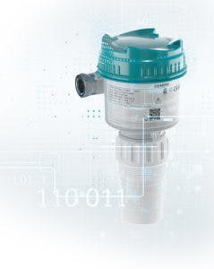
Operators removed the existing guided wave radar device and installed the SITRANS Probe LU240 transmitter, even considering the narrow space restrictions between pipes.
Once the device was set up, the water level was lowered to expose the troughs. Operators activated the backwash cycle, which created a turbulent surface due to the airflow that is part of the process. During this critical time and subsequent cycles, the ultrasonic level transmitter tracked the level accurately.
The echo signals captured using SIMATIC PDM diagnostics software utility showed that at the lowest level, the transmitter could see the pipes, but they did not cause interference with the level measurement. In fact, the echo signal reflecting from the water surface was so strong, operators did not need to apply the instrument’s Auto False Echo Suppression capabilities to negate the reflections caused by the pipes and troughs.
Back in the control room, operators compared the performance of the new transmitter to the remaining guided wave radar transmitters in the other filter beds. The transducer section remained clean, and the historical trend graph showed consistent level measurement.
Based on these results, operators removed another guided wave radar transmitter on a nearby filter bed. Both of the new transmitters have been operating under the same conditions as the previous guided wave radar transmitters.
This maintenance-free solution and consistent performance showed that ultrasonic level technology was the right choice for this and many level applications found in the wastewater treatment process.
