Many industrial processing plants use seawater for a wide range of applications, including cooling purposes. A chlorination package (or a sodium hypochlorite package) should function to inhibit algae and other marine growth in the seawater supply system and should be capable of providing continuous shock chlorination. Chlorination dosing systems are often provided in package formats, which can include bulk chemical storage tanks, chemical bunding, dosing pumps, chemical residual analyzers, electrical control panels and others. The required chemical for dosing is usually generated through electrolysis of seawater. Required concentration and seawater properties are important data for any chlorination package.
Monitoring and continuous operation of the package are needed for many applications. The usual expectation is that the dosing process should be fully automated and controlled so it can be operated and monitored from the plant’s main control room.
Sodium hypochlorite, chlorine and dosage
Sodium hypochlorite is a chemical compound with the formula NaCIO. It is composed of a sodium cation (Na+) and a hypochlorite anion (CIO−). It may also be viewed as the sodium salt of hypochlorous acid. When dissolved in water, it is commonly known as bleach or liquid bleach. Sodium hypochlorite is practically and chemically distinct from chlorine; however, sometimes either term is used because they have more or less the same effects. Sodium hypochlorite is frequently used as a disinfectant or a bleaching agent and can be formed by reacting sodium chloride with oxygen gas.
The most commonly used chlorination system provides on-site generation of sodium hypochlorite by partial electrolysis of the sodium chloride contained in seawater. Seawater flows into a cell equipped with electrodes (anodes and cathodes) energized with direct current. Chemical and electrochemical reactions then occur.
The concentration of injected chlorination gradually decreases due to a reaction with organic matter and other oxidizable substances. The dosage should be controlled at the seawater intake according to the residual analyzer installed at the seawater outfall channel in order to achieve the required residual concentration.
As a rough indication, dosing concentration at the seawater intake system might be around 1.6 to 1.8 parts per million (ppm); residual chlorine at the outlet could be around 0.4 to 0.5 ppm. Shock dosing should achieve two times more than the normal dosing concentration (3 to 3.5 ppm). As another rough indication, the generator provides the capacity of around 18 kg/h of continuous chlorination for each 10,000 m3/h of seawater. For instance, a processing plant that needs around 20,000 m3/h of seawater might need the chlorination package of generation capacity about 36 kg/h.
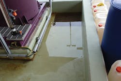
Figure 1. Bottom section of a chlorination package. Courtesy of Amin Almasi
Hypochlorite generator systems
Booster pumps push seawater into a seawater filtration system and then into a hypochlorite generator assembly. Seawater booster pumps are usually centrifugal pumps, which increase the seawater pressure to approximately 5 to 6 barg. Seawater booster pump materials also need attention. These pumps are usually made of super duplex stainless steel casings, impellers, shafts and wear rings to offer reliability and availability.
Before entering the electrolyzer module, an auto-backwash filter system removes solid particles greater than 0.5 mm. Some fine multistage filtration systems are designed for better than this — sometimes down to 0.1 mm. The auto-backwash seawater filter is monitored by a differential pressure transmitter. As soon as the differential pressure across the clogged filter reaches the setpoint of the high pressure differential transmitter (0.5 to 0.7 bar), the backwash sequence starts.
The hypochlorite generator assembly usually consists of cell modules to form independent subunits with standard generating capacity. One spare generator is commonly specified for many systems; this is known as the N+1 arrangement. Commonly used plans are 1+1 (one operating, another spare) or 2+1 (two operating at 50 percent, another 50 percent spare). The generators should be sized so there is at least one spare generator at the time of maximum demand, most often at the time of shock dosing. This is to ensure that there is N+1 equipment available during shock dosing. Generally, the internal and overall arrangement of the generation cells should provide maximum rectification efficiency while preventing possibility of stray current corrosion.
The most commonly used chlorination system provides on-site generation of sodium hypochlorite by partial electrolysis of the sodium chloride.
Generation cells contain sensitive and sophisticated internal parts such as anode and cathode elements, complicated electric power systems, etc. An important feature of an electrode assembly is the ease of replacement of an electrolyzer cell, in a short time, without the need for special equipment or specialized manpower. The electrolyzers operate normally under constant seawater flow rate, while DC load (current) is manually or automatically adjusted to meet the required production of active chlorine. In commonly used generation systems, each electrolyzer consists of electrolytic cells of modular construction. These are combined in electrical and hydraulic series and fastened together to form an electrode assembly, which is placed in a FRP/PVC-lined reinforced body.
Electrodes in generation cells should be protected against a drop in seawater flow below the minimum requirement and high temperature rise in the hypochlorite generator above safe level. If such events occur, the power supply to these electrodes should be cut off immediately to prevent damage. Flow transmitters in each train before the electrolytic cells monitor electrolyzer flow rates and provide low flow signals to protect the electrolyzers.
Each cell should be designed for the seawater booster pump shutoff head, plus a suitable margin, and it should be capable of withstanding a test pressure of 150 percent of this design pressure. Relief valves are also needed for protection. Anode and cathode elements are expected to operate for a minimum of five years. Theoretically, an inspection window is specified for the generator to internally detect any deposit built up between the anode and cathode. In most cases, the inspection window is not recommended, as generated H2 will be trapped and the window will be unclear overtime.
Storage, handling and injection systems
A sodium hypochlorite solution storage tank is needed to store the generated solution for injection. Different guidelines for the sizing of the solution tank have been introduced. The tank should usually be sized with consideration for 5 to 20 minutes of storage for shock dosing (maximum demand case).
The residence time of an incoming hypochlorite solution is an important consideration, for instance, to remove entrapped hydrogen gas in the fluid stream. Three to 15 minutes (sometimes more) have often been specified for this hydrogen gas removal requirement.
Hydrocyclones are sometimes recommended to remove entrapped hydrogen gas in the fluid stream and to release it safely into the atmosphere via vent pipe or flare. Many vendors have degassing tanks and air blowers for the removal of H2 without a hydrocyclone.
This design can successfully operate if the system is designed properly. The sizing of the tank is extremely important and is usually designed with tangential inlet flow, which will enhance the separation of H2 from the solution. In addition, 2×100 percent (one operating and another standby) air blowers should be provided to dilute the H2 to less than 1 percent level before venting out of the degassing tank. The lower explosive limit (LEL) of a hydrogen/air mixture is usually 4 percent hydrogen; therefore, the 1 percent level is far on the safe side. One blower is set on continuous operation, and the second blower is set on automatic standby.
Inlet filter screens prevent unwanted dust or debris from being admitted into the vent system. An airflow transmitter placed on the blower discharge side provides logic feedback for the standby blower startup. In the event the operating blower fails, the standby blower should start automatically. If both air blowers fail, the DC current supply to the generators will be cut off and stop the electrolysis process after the predetermined delay and no H2 will be produced.
Flame arrestors have often been specified to be installed in the vent lines. However, flame arrestors are not recommended as the electrolysis byproduct (such as CaCO3, MgO, etc.) precipitates will choke the flame arrestor elements, which could create a maintenance issue.
Injection pumps can be centrifugal pumps or positive displacement pumps. For small packages, positive displacement pumps are preferred. The fact is, for many large plants, seawater flow, and consequently the sodium hypochlorite flow rate, are so large that medium-sized centrifugal pumps should be employed for the injection. If centrifugal pumps are selected, pump characteristics and curve should be selected with great care; proper study should be completed to ensure trouble-free operation of these centrifugal pumps used in difficult injection services. If positive displacement pumps are selected, they should usually be API-675 pumps. This is a necessary requirement, considering low reliability and availability of non-API positive displacement pumps.
Centrifugal pumps should operate in parallel for injection applications. Checking parallel operation is needed because it might affect pump capacity. The flow of two identical pumps in parallel operation is less than two times the flow of each. The minimum flow lines for centrifugal pumps require care.
Sealless pumps used for chemical injection services can present some challenges and operational difficulties. Nowadays, centrifugal pumps with proper mechanical seals are more popular. Shaft seals should be selected carefully, as it can be difficult to select seals for chemical services like sodium hypochlorite. A properly selected API seal plan is always preferred. The mechanical seal and selected seal plan should guarantee leak-free and long-term pump operation. There have been many seal failures in exotic chemical services like sodium hypochlorite applications.
A processing plant that needs 20,000 m³/h of seawater might need the chlorination package of generation capacity about 36 kg/h.
Diffusers should be located at the seawater intake systems for quick and uniform dispersion of the hypochlorite solution into the seawater flow. In a successful design widely used in various plants, the diffuser piping is both internally and externally hard rubber-lined and flanged at one end for connection to the diffuser pipe regulating valve. This design is used to minimize interference with the seawater flow; it should be of sturdy design to resist flow strain.
Performing hydraulic calculation from the injection pumps to the diffusers ensures required pressure is achieved for proper dosing for each injection point. Recommended sodium hypochlorite solution velocity should be 1.5 to 2 meters per second (m/s). Many factors should be considered for a proper and successful diffuser design, such as seawater flow profile, operating depth in seawater bay/flow, etc. Diffuser design is a mixture of engineering, science and art.
Control, auxiliaries and accessories
For modern packages, the entire process of hypochlorite generation and injection for continuous dosing should be designed for automatic control. A residual equivalent chlorine analyzer and controller units should be provided to continuously monitor the hypochlorite production rate with changes in seawater flow rate, temperature and salinity. A proper controller unit should be included to automatically vary the hypochlorite generation rate when a change in residual equivalent chlorine is detected in the analyzer units.
There are different instruments, measurements, valving and actuator systems that should be properly designed and implemented. Installing a flowmeter upstream of a control valve ensures it is always liquid-filled. Otherwise, there would be the risk of running half-open downstream of the control valve.
Acid cleaning systems
Some cations present in seawater (calcium, magnesium and other metals) form hydroxides and carbonates — resulting in suspended solids — which are mostly carried out of the electrolyzer by the chlorinated seawater stream. Due to deposit formation on the electrode surface, the electrolyzer units should undergo periodic cleaning with diluted hydrochloric acid (6 percent w/w). In chemical literature, hypochlorite concentrations are in terms of available or active chlorine (the quantity of chlorine has the same oxidizing effect as the hypochlorite when analyzed by standard method).
An acid cleaning system or the occasional cleaning of the hypochlorite generator cells are required. The system should provide a collection tank for the used acid to be neutralized after cleaning. Such a system should be designed and operated with great care since it handles acids. The necessary facilities and equipment should be safe and compliant with the standard practice of the chemical industry and local authority requirements. An acid cleaning system should have a tank and pumping system to do these tasks.
The acid cleaning pump should serve to pump acid from the acid cleaning tank through the hypochlorite generator cells and to the acid-neutralizing tank. This process may be in a back-flushing direction to improve cleaning efficiency. Pump materials should be acid-resistant. Same as the centrifugal pumps for the injection services, sealless pumps have been used for this service; however, pumps with proper mechanical seals are more popular. Shaft seals should be the mechanical seal type and should be leak-free. Pump flow and head should be selected to ensure proper cleaning of the generator cells without damaging them.
The neutralized acid will be disposed of via drums of suitable size located outside sodium hypochlorite package building. Suitable acid-resistant lining of floors and bund walls with sump pits should also be provided.


