The purpose of this article is to provide a way to calculate all the data necessary to determine the performance of a fan-driven air process cooler. Although these coolers are available at the present time, the fans use flat blades that cannot direct air downward and parallel to the walls of the containment vessel. As a result, air impingement of the vessel walls occurs, which creates friction and turbulence that reduces the fan-generated pressure and decreases the availability of heat transfer surfaces and, therefore, the amount of heat that can be extracted by those surfaces.
Water reuse for cooling purposes
When an end user requires a readily available cooling medium for industrial or residential requirements, water is probably the first medium that comes to mind. Unfortunately, water, particularly clean and drinkable water, is quickly becoming a scarce medium because of pollution, increased irrigation demand and drinking water requirements to sustain the ever-growing world population.
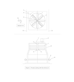
To overcome these problems, one solution that is used effectively in industrial applications is to reuse or recycle the water presently used for cooling purposes. This requires the use of additional process equipment, such as cooling towers, that use cool atmospheric air to partially evaporate some of the cooling tower water to achieve product water at a temperature suitable for reuse in the cooling equipment used. In chemical processing, this recovered and cooled water may be used to produce an end product that is exported to end users. Figure 1 shows the description and arrangement of each composite part of a process cooler.
Component arrangement (description of figure 1)
| Number | Description |
|
1 |
Fan blades should have a 90-degree curve, so the air enters and leaves the rotating blades at right angles. This provides a downward movement of air within the surrounding containment vessel. The fan has eight blades (2 feet wide and 11 feet long). The arrangement provides two, four-bladed staggered rows located one above the other with all eight blades in the arrangement equally spaced. |
|
2 |
The air containment vessel has a 22 foot diameter upper section and a 24-by 24-foot lower tube housing section. |
|
3 |
The containment vessel houses a single row of uniformly spaced horizontal tubular heat transfer elements, with or without extended surfaces, in the form of fins. A total of 36 tubes, each with a 4.5-inch outside diameter, spaced 8 inches center to center, are included in the present design. |
|
4 |
The fan blades rotate counter-clockwise. |
|
5 |
Cross-sectional view (A-A) of the fan blades is shown. |
|
6 |
The fan includes a 250-horsepower electric motor or comparable drive device. |
|
7 |
The electric motor gear drive provides much lower rotational speed that the fans, than would be available using electric motors of standard design. |
|
8 |
Fan axle’s diameter facilitates the attachment of the multi-bladed fans. |
|
9 |
Horizontal row of tubular heat transfer elements housed in the containment vessel. |
|
10 |
Tubular manifolds for the entire row of tubes are included in the design shown, as would be acceptable for a steam condenser. However, a multiple stream arrangement could be used if it were found necessary to do so. |
|
11 |
Axle bearings |
|
12 |
Appropriate structural steel framework for the entire cooler assembly |
|
13 |
The desired downward movement of air jets, parallel to the vertical walls of the containment vessel, is made possible by the curved fan blades. |
|
14 |
Centerline of the inlet and outlet manifolds for the tubular cooling element manifolds |
Use in power generation
Power generation plants produce high-pressure steam that, when expanded in a turbine, generates enough energy to power electricity-producing generators. To condense the turbine steam for reuse, tubular water-cooled steam condensers are almost invariably used, making power plants large users of cooling water. The cooling water for these condensers is recycled to a cooling tower, in which air cooling occurs. Only a sufficient and small amount of makeup water is necessary to be added to the cooling tower product to provide enough water for the turbine exhaust steam condensers to function properly.
Performance has been determined for a typical air cooled tubular steam condenser, of relatively small size, but a larger version, or multiple smaller versions could be used in a power plant of typical capacity with approximately 50- or 100-megawatt (MW) output.
The performance data for a cooler like the one in Figure 1 is calculated in equations 1 through 14, listed below. The cooler is a shop-assembled type, perhaps 20 to 30 feet in overall width and height, but a shippable size would depend on the cooler’s ultimate location.
- Fy = (Q)(Dens)(Vb)(Sin 90 deg)/g1
- Ab = (Nb)(Wb)(Lb)
- (Ab)(Vb) = Q
- (Vb) = [(2)(Lb)/(2)](RPM)/(60)
- [(Q/0.785)(Di)2)] = Va
- HPa = (Fy)(Va)/550
- AT = [(dt)/(12)](nT)(lH)
- Nt= (Lh)(12)/Do
- Aj = [(Lh)(Lv) – AT]
- Vj = Q/Aj
- Fj = (Cd)[(Vj)2 /(64.4)](Dens)(Lh)(Lv)
- HPj = [(Fj)(Vj)]/550
- ho = 0.133(Cp)(G)0.6/Dt0.4
- qair = (Ubare tubes)(Rfins)(Abare)(LMTD
|
Table 1: Nomenclature for cooler performance data equations |
|
Fy = Downward force exerted by fan blades in pounds (lb) Q = Downward air flow in cubic feet (ft3)/sec Dens = Density of air in lb/ft3 Vb = Downward fan blade velocity in feet/second (ft/sec) Sin 90 deg = Sin of the angle between the horizontal and vertical blade elements Ab = (Nb)(Wb)(Lb) = Total vertical fan blade area in square feet (sq. ft.) Nb = Number of fan blades Wb = Blade height in feet Lb = Blade length in feet RPM = Blade revolutions per minute Di = Inlet diameter of the upper section of the cooler in sq. ft. Va = Downward air flow velocity in the upper section of the cooler in feet per second HP = Fan drive horse power AT = Total cross-sectional tube area in sq. ft. DT = Tube diameter in inches NT = Total number of tubes LH = Tube length in feet Do = Center to center tube spacing in inches Aj = Free area between tubes in sq. ft. Lh = Inside length of bottom tube housing in feet Lv = Inside width of bottom tube housing in feet Vj = Air velocity between tubes in ft/sec Fj = Force generated by velocity of air between tubes in lb Cd = 1= Tube drag coefficient, a function of the air velocity between the tubes HPj = horsepower generated by the air velocity between the tubes ho = Tube outside heat transfer coefficient in BTU per hour, sq. ft.-degrees Fahrenheit Cp = Specific heat of air, BTU/lb-degrees Fahrenheit G = Lb/hour-Sq. ft. Dt = Tube diameter in feet qair = Cooling heat duty in BTU per hour. Ubare tubes = Bare tube overall heat transfer coefficient in BTU per hour, sq. ft.-degrees Fahrenheit Rfins = 5/1 = Ratio of fin to bare tube area Abare = Total bare tube area in sq. ft. LMTD = Natural log mean temperature difference |
Conclusion
Findings from the equations 1 through 14, mentioned above, indicate that the calculated heat duty for the subject cooler — using an air flow generated by a multi-blade fan, driven by a 250-horsepower electric motor — will have a cooling capacity of 32 million British thermal units (BTU) per hour. Although the cooler can have bare tubes installed, using a single row of finned tubes with a five-to-one ratio of finned-to-bare-tube surface provides a more cost-effective choice.
Reference:
- R. C. Binder, Fluid Mechanics, 2nd Edition, Prentice Hall, Inc., N.Y.
Alan Cross received a B.Ch.E. degree from the City College of New York and an M.S.Ch.E. degree from NYU Polytechnic School of Engineering of Brooklyn. Cross is a long-time member of the American Institute of Chemical Engineers and has more than 30 years of experience in the design of direct fired process heaters, while in the employment of the Abb Lummus Heat Transfer Division of Abb Lummus Crest located in Bloomfield, New Jersey. He has since written and published about 10 design articles relating to heat transfer, fluid flow and a variety of other topics, and has authored and received five U.S. patents.


