Dome-loaded regulators for pressure control applications
Recent advances in membrane purification and water management systems have required increasingly sophisticated process control systems. Many applications in both industry and the laboratory require more stable pressure control and are progressively adopting computer automation to improve precision, capture better data and save labor. A common challenge is finding effective pressure control methods that perform reliably and are easily automated despite widely fluctuating flow rates, wide pressure ranges, temperature extremes, phase changes or aggressive chemistry.
These issues can require system designers to consider alternative approaches that go beyond traditional spring-loaded valves and other manual devices. In many cases, dome-loaded pressure regulators offer a good solution.
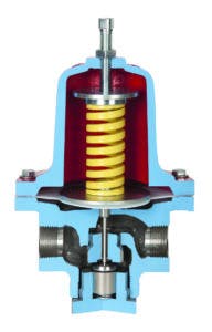
Figure 1. Spring-loaded globe-style regulator. Courtesy of Jordan Valve
Traditional spring-loaded regulators
A traditional spring-loaded valve is generally the first option an engineer will consider because it is familiar and provides reliable pressure control for most simple processes. In this design, a compressed spring is the loading mechanism that balances force against pressure on a diaphragm or piston. Small imbalances on the diaphragm or piston result in the valve opening or closing. The spring is compressed to the desired setpoint by manually turning a knob or a screw (see Figure 1). It is self-operated and relatively small, which offers advantages.
While economical and sturdy, these devices do not always perform well in complex situations where automation or higher performance is required. Precision is typically limited with varying flow due to the varying spring constant as the valve opens. Most designs above 10 bar incorporate O-ring seals, which can add friction and therefore, hysteresis to the performance.
Dome-loaded regulators, on the other hand, receive their setpoint from a fluid pressure on the dome, which offers specific advantages for challenging applications.
How dome-loaded regulators work
A dome-loaded regulator uses a fluid pressure, normally air, on top of a sensing element to provide the setpoint pressure. The sensing element is typically a diaphragm (common for lower pressures) or a piston (common for pressures above 10 to 20 bar). In simple dome-loaded regulators, a single sensing element separates the process fluid from the dome fluid, and the pressure imbalance drives the valve position.
The pressure of the fluid fed to the dome is set by a second regulator called a pilot regulator, which could be a manual air regulator for manual applications or an electronic pressure regulator for computer automated applications. The electronic pressure regulator, or electro-pneumatic regulator, takes the input signal from the computer and translates it into a pressure that is fed to the dome of the dome-loaded regulator (see Figure 2).
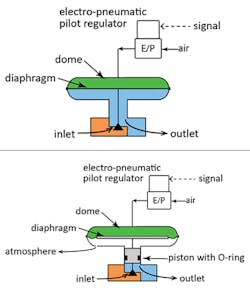
Figure 2. (Top) Simple 1:1 dome-loaded regulator with electronic pilot regulator. Figure 3. (Bottom) Dome-loaded regulator with pressure ratio. Courtesy of Equilibar
Dome-loaded regulator with pressure ratio
For higher pressure applications, it can be convenient to dome load with available lower pressure air, for example 0 to 7 bar, while controlling the process at higher pressures such as 0 to 100 or 0 to 200 bar.
This is accomplished by using separate sensing elements on the dome and on the process. The dome sensing element has a larger diameter than that of the process pressure sensing element, creating the pressure ratio (see Figure 3). For example, a 30:1 pressure ratio regulator would allow computer automated control of 0 to 3,000 psig using a 0 to 100 psig electronic air regulator.
Advantages of dome-loaded designs
With the increasing adoption of process automation, the primary advantage for the dome-loaded design is its ease of computer automation using an electronic pilot regulator. Dome-loaded designs also typically improve precision by delivering a more constant force (pressure) as the valve position varies. Some dome-loaded designs also benefit by the complete elimination of O-ring friction and hysteresis.
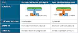
Figure 4. Comparing pressure reducing regulators to back-pressure regulators. Courtesy of Equilibar
Pressure reducing regulator versus back-pressure regulator
Dome-loaded regulators are available as either a pressure reducing regulator (PRR) or a back-pressure regulator (BPR). Despite the seemingly straightforward differences between the two, even experienced engineers and researchers sometimes have difficulty determining the one they need.
A PRR — the more common type — can be referred to as a forward-pressure regulator, pressure reducing valve or simply a pressure valve. PRRs reduce a higher supply pressure at the inlet down to a lower outlet pressure and control the downstream pressure. They open to increase downstream pressure and close to decrease downstream pressure.
In contrast, a BPR, sometimes called a pressure sustaining valve or a back-pressure reducing valve, maintains a defined pressure upstream at its own inlet. BPRs work similarly to relief valves, but the emphasis is on steady-state pressure control instead of on/off actuation. They open to decrease upstream pressure and close to increase upstream pressure. BPRs are extremely useful when placed downstream of a membrane to control the retentate pressure (see Figure 4).
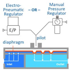
Figure 5. Multiple orifice dome-loaded back-pressure regulator. Courtesy of Equilibar
Dome-loaded BPR with multiple orifice design
A newer type of dome-loaded back-pressure regulator uses an innovative design in which the diaphragm covers a field of parallel orifices located in the body of the regulator. As fluids flow through the unit, the diaphragm lifts off the orifices to release pressure. When flow is minimal, only a portion of one orifice will open to release the pressure. When flow is high, the diaphragm is pushed up to engage all the orifices (see Figure 5).
This flexibility results in exceptionally wide flow range that can provide solutions for even the most extreme back-pressure control scenarios. The design can hold pressure stable across extremely wide flow ranges such as 1,000:1 and beyond 100,000:1 in many processes. The frictionless diaphragm avoids all hysteresis, allowing for highly precise control in manual, open-loop or closed-loop control systems.
Case study No. 1: Water cooling in a steel processing facility
A steel mill in Europe uses water to cool sheets of steel as they are rolled and flattened to their target thickness. Different grades and thicknesses of materials require different volumes and pressures of water for effective and efficient processing. Traditional plant design was to vary the water volume using control valves located in the mill’s water control room, far from the actual cooling point.
The mill’s technical team hypothesized that if they could more accurately regulate the water volumes and provide more points of water release, they could both improve overall steel quality and increase throughput. To accomplish this, they designed a system of dome-loaded PRRs installed side-by-side to control pressure across the breadth of the process (see Figure 6). Point-of-use dome-loaded PRRs were an ideal choice because:
• The significant rangeability of the dome-loaded PRR covers the broad spectrum of pressures required for cooling parameters of the different products.
• Changing the setpoint (outlet pressure) of a dome-loaded PRR for a specific process requirement is as simple as changing the air pressure supplied to the dome.
• There is no restriction on the install orientation of a dome-loaded valve. (Note: Three of the five PRRs in each unit are installed "upside down.")
"After the dome-loaded PRR solution was tested and ultimately implemented, this mill increased overall production speed by 60% and achieved increased material conformity across the length and width of their steels," said Charles Page, vice president of Richards Industries, a manufacturer of pressure regulators and other flow control products. "They’re now making plans to repeat this success at many of their other facilities."
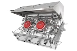
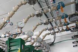
Figure 6. A series of dome-loaded PRRs were installed in a steel mill processing plant to control cooling water. Courtesy of Jordan Valve
Case study No. 2: RO membrane fouling research
Scientists working to improve desalination and remediation of water have had success using a dome-loaded multiple orifice BPR to control pressure on a membrane used in reverse osmosis (RO). The goal of this research, which is being conducted at a flagship American university, was to increase understanding of RO membrane fouling in order to predict and improve membrane performance. The experimental setup required precise membrane pressure control across a wide range of pressure, flow and salinity conditions. For instance, process conditions involved sodium chloride solutions at saturation levels from 3.5% up to 26% and included solutions with sodium alginate, both dissolved and as gel particulates.
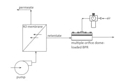
Figure 7. Sketch of RO research setup using multiple orifice dome-loaded BPR in the retentate line for precise membrane pressure control. Courtesy of Equilibar
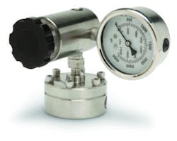
Figure 8. Multiple orifice dome-loaded BPR with manual pilot regulator and pressure gauge. Courtesy of Equilibar
The researchers had previously used a needle-style globe valve but found that it tended to clog, causing unacceptable variations in pressure control. The new BPR with the multiple orifice design avoided the clogging problem and helped to eliminate noise in the data. The multiple orifice dome-loaded regulator was a good choice for controlling the pressure of the RO membrane because the frictionless control from this BPR design delivered precise pressure control, even with fluctuations in process flow (see Figures 7 and 8).
"For this application, using the new BPR provided accurate membrane pressure control for the RO research, allowing the testing to proceed without supervision or adjustment," said Tony Tang, engineering manager for Equilibar.
Key factors for choosing dome-loaded pressure control
Because a second regulator is required to pilot a dome-loaded regulator, this approach will not always be the best choice; however, an engineer or scientist with a complex pressure control problem may want to consider a dome-loaded regulator when automation is involved in the application or when faced with widely varying flow rates or other demanding application parameters.