Pumps, Motors & Drives: Pumping System Optimization
by William C. Livoti
Runaway energy prices are pushing plant operating costs through the roof. This increase is due to record U.S. electricity use. New power plant construction and ever-increasing fuel costs will further increase the price of electricity.
Industrial motor systems are the single largest electrical end-use category in the U.S. economy, with motors accounting for 25% of electrical sales. These values come from the U.S. Industrial Motor Systems Market Opportunities Assessment, 1998 (DOE).
Over 60% of industrial motor-driven system energy consumption involves fluid handling. Pumps, fans, compressed air and refrigeration devices account for 36.8% of the industrial population and 61.0% of the industrial motor energy consumption. A small fraction of the motor population is responsible for most of the energy consumption. Energy is the dominant cost of ownership.
This article focuses on total pumping systems optimization with an emphasis on improved “Life Cycle Costing” using variable frequency drives (VFDs) and premium efficient motors.
Efficiency & Reliability
What is system optimization and why is it important? Pumping system optimization is the process of identifying, understanding and cost effectively eliminating unnecessary losses while reducing energy consumption and improving reliability in pumping systems.
The overall efficiency of a system is the product of efficiencies of each energy component along the way. Optimizing one or the other of the individual components (component optimization) may improve overall efficiency, or it may reduce it, because it could cause one or the other components to operate in a less efficient mode. Therefore, any effort toward reducing energy consumption and cost has to take the entire energy flow train into consideration. System optimization involves looking at how the sub-systems function together and how changing one facet can contribute to increasing overall system efficiency.
There are factors other than just efficiency to consider – reliability and uptime for example. In many industrial applications, reliability and productivity is a more important consideration than efficiency.
Basic Pumping Facts
Typical system issues include:
- Systems controlled by throttle valves/dampers
- Recirculation line normally open
- Cavitation noise at valve or pump
- Systems with multiple parallel pumps with the same number of pumps always operating
- Constant pump operation in a batch environment or frequent cycle batch operation in a continuous process
- Systems that have undergone a change in function.
- High system maintenance
- Motor tripping out
Optimal Case Study
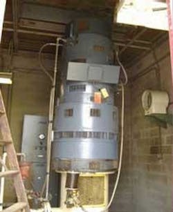
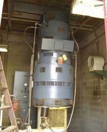
A well system installed in May 1975 is comprised of two separate installations designated 1B and 1A. Subject units are vertical, six stage turbine style pumps. Said units are coupled to 250-hp motors through an eddy-current drive. The pumps develop 310 ft head @ approximately 1,700 gpm when operating at base speed of 1,717 rpm. The system generally operates in the 1,200-1,700 rpm range. Under extreme conditions, however, the pumps can run at a higher rate/speed. The well pumps feed water into several areas of the plant.
Summary of Existing Configuration:
The eddy-current drive couples an eddy-current clutch to an AC induction motor. A rotating drum connected to the induction motor surrounds a cylinder attached to the output shaft. The concentric cylinder and drum are coupled by a magnetic field, whose strength determines the amount of slip. Speed is controlled by a low-power solid-state device that shifts the current in the magnetic field winding. This field excitation typically consumes 2% of the drive's rated power.
The eddy-current clutch is a slip device like the hydraulic coupling, but more efficient. Waste heat, generated by the motion of the drum and cylinder, is the main source of power loss. This is controlled some what with air or water cooling.
The hollow shaft motor with pump shaft extending through said motor doesn't allow for precise alignment/centralization of pump shaft to motor bore.
Scope of work:
- Equipment tested
- Procedure/process
- Tools utilized
- Deliverables
Components to be reviewed:
Electrical ASD (eddy-current drive) – High potential for savings
Motor (50-hp and above) – The motor size has little effect on overall system efficiency if motor is slightly over-sized.
Coupling – Losses should be minor, however, imbalance can result in energy loss and premature failure
System – Static or friction?
Pump – Is the pump sized correctly for the system, component upgrades, repair history?
Control valves – Type of valve, is it throttled?
Piping and fittings – System configuration, big savings potential, Ultimate Goal (every application has its own unique ultimate goal).
Sole plate/installation – Integrity, level, impact on pump and motor reliability
Test Procedure:
After a group of priority systems has been identified, the next step is to take the necessary measurements. Testing will be conducted by Baldor Electric upon plant safety and procedure review with plant personnel. Plant/customer will be required to supply specific information (as noted below).
Tools and information:
- Analog pressure gauges – (calibrated) installed at suction and discharge of pump. Spare gauge will also be required for moving from location to location to obtain spot checks
- Amp meter/volt meter – To obtain readings from motor under various load ranges during operation
- Flow meter – Ultrasonic or intrusive
- Motor – name plate data
- Pump – name plate data
- Pump Curves – (customer)
- System Curve – (developed by Baldor Engineering)
Deliverables:
- List of systems assessed
- System operating data
- Screen shots of data as compiled in energy assessment software
- Developed system curves based on above data and hours of operation
- System evaluation and assessed potential for energy savings
- Recommendations (based on two year ROI)
- Work scope for recommendations
- Price and delivery for implementation of recommendations
Discussion
According to the plant P&ID's the well pumps send water into the water treatment facility, upon entering the facility the pressure is reduced to 25 psi by valve PRV-1 and PRV-2, flow is then directed to the clear well, flush water and chlorination systems. Therefore, it was assumed the treatment plant only required a maximum of 25 psi through the 8" line feeding the plant.
Operating performance and energy calculations were obtained at three operating points. Friction loss was calculated across valve PRV-1 at the three operating points (1,200-, 1,500- and 1,717-rpm).
Observations:
Savings/Benefits:
This speed change would eliminate the need for excessive throttling of valves PRV-1 and PRV-2. The spread sheet contains projected annual energy savings as well as maintenance cost at various operating points. All savings calculations are based on operating at specified points 33% of the time @ 8 cents per kWh (national average).
The variable frequency drive and motor upgrade provide the flexibility of altering the flow rate of the pump, however, the system (downstream) ultimately controls the overall system efficiency as outlined in the discussion segment of this report.
Eddy-current drive/VFD/motor conversion:
- Maintenance – Motor, drive and pump repair, reduced vibration
- Reduced slippage – 2-10% (eddy-current drive), reduced vibration and maintenance
- Wide range of operation – Maximize savings by controlling system with pump speed rather than control valve
- Solid shaft premium efficient motor – 2 points of efficiency, precision alignment capability, reduced vibration, improved MTBR
- Rigid coupling motor to pump – Precision balance, precision alignment, reduced vibration
- VFD – Improved efficiency, eliminated component between motor and pump reducing overall height of installation, wider range of programming/control of process
Summary of Savings
Maintenance history:
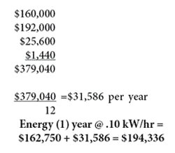
- Frequent drive failures MTBR 1 year ($5K) = $160,000
- Pump MTBR 2.5 years ($15K) = $192,000
- Motor repair 2.5 years ($2K) = $25,600
- Lost production $ = ?
- Maintenance/Labor = 16 hours x 2 = 32 man hours x $45 = $1,440
null
Total savings:
Maintenance per unit: $31,586.00 (per year)
Energy per unit:
- Premium Efficient Motor – $5,861.00 (95.80%)
- Friction Loss – $31,306 (average over three operating conditions)
Total Savings per year = $68,753 x (2) units = $137,506.00
Conclusion
Overall efficiency of a system must be taken into consideration to achieve optimum energy savings, reliability and sustainability. The importance of evaluating the total system is taking into consideration how the subsystems function together and contribute to increasing overall system efficiency. This particular case study exemplifies this concept. As stated in the introduction, factors other than efficiency should be considered such as reliability, uptime and productivity.
Acknowledgments: This article was prepared on behalf of the Hydraulic Institute's Pump Systems Matter initiative, which includes Baldor Electric Co. as a sponsor. Developed by the institute, PSM is an educational initiative to help North American pump users gain a more competitive business advantage via strategic, broad-based energy management and pump system performance optimization. Contact: www.PumpSystemsMatter.orgAbout the Author: William C. Livoti is senior principal engineer of Power Generation and Fluid Handling at Baldor Electric Co., of Fort Smith, AR. Baldor is a leading maker of industrial electric motors in North America and has 28 manufacturing sites worldwide. Livoti works at its Baldor Dodge Reliance Division in Greenville, SC. Contact: 864-281-2118, [email protected] or www.baldor.com


