Ditch Lining System Resolves Stormwater Erosion Issues
Dealing with onsite stormwater issues in industrial settings simply cannot be avoided. It comes with the territory. The entrance ways, exits and immediate surrounding footprint of many industrial sites, such as small refineries, waste transfer sites and power substations, typically are a combination of concrete slabs, excavated clay, soil and gravel. The stormwater runoff and perimeter drainage plan usually consists of a series of shallow earthen trenches.
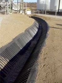
Two recent projects made use of a relatively new HDPE ditch lining system to help control stormwater flow.
Ethanol Plant800 feet of the HDPE ditch lining system was installed at the power sub-station to control excess stormwater runoff from local hillsides.
Last August, an ethanol plant in western Canada that produces 130 million liters of ethanol annually experienced the “perfect storm” when it was hit with 2.5 inches of heavy rain in less than 3 hours. The plant’s drainage system consisted of an intricate series of aggregate-lined ditches and swales that were strategically placed throughout the site. The aggregate proved to be too fine and instead incurred a high rate of erosion. The scoured aggregate plugged culvert drains and caused flooding over the ditches and swales. As the deluge continued the flooding threatened plant operations and eventually did destroy valuable by-product in a storage shed. It became apparent that the current stormwater drainage plan was not working.
In search of a better solution, the plant owner sought the advice of a local drainage and stormwater products distributor. After conducting some research of the available technologies on the market, the distributor recommended a trapezoidal-shaped HDPE ditch lining system called SmartDitch.
Non-Traditional Solution
There were some unique conditions at this site that made the HDPE ditch liner the ideal solution for this particular application.
- The trapezoidal shape of ditch liner was a close fit to the existing earthen channel profile, simplifying the installation process.
- The channel’s physical make-up and ribbed design would create a corrosion free, leak free ditch with good water flow control capabilities, all of which are critical in industrial environments such as this one.
- The HDPE ditch liner would eliminate any scouring of aggregate, silt, or soil that is naturally inherent with earthen ditches.
- The system could be field fabricated to conform to the plant’s complex maze of earthen drainage channels, enabling it to tie in with the existing drains, valves and containment weirs that ultimately fed into the retention ponds.
A total of 2400 feet of the 24" depth ditch liner was placed throughout the ethanol plant’s storm drain system.
Power Sub-Station
When Rocky Mountain Power’s White Rock power sub-station was constructed in northern Utah, it included a stormwater drainage system that met the local guidelines and regulations. However, what wasn’t known or planned for at the time was additional, unregulated, hillside stormwater runoff that was co-mingling with the site’s regulated stormwater; subsequently increasing the owner’s disposal costs.
To arrest this, Power Engineers, the consulting engineering firm on the project, specified the installation of 800 lf of 12" SmartDitch to keep the hillside drainage separate from the site’s mandatory stormwater drainage system. The addition of the HDPE ditch liner also helped stabilize this new perimeter drainage system’s sidewalls, and minimized any future erosion or sediment runoff.
Typical Installation Scenario
In both projects, the installation process was similar. Once the contractor excavates and cleans out the existing ditches/swales, the 10-foot ditch liner sections are dropped into place. Gaskets are then applied to the upstream end of each section. Once that is complete, the downstream end of another 10-foot liner section is overlapped and joined with a series of stainless steel self-tapping screws. This process is continued until the job is finished. A cable anchoring system (similar to that of a retention wall anchoring system) is then used to secure the HDPE ditch liner into the ground.
For more information on the SmartDitch system, manufactured by Penda Corp., visit the company’s website at www.smartditch.com.


