Tips on Sizing a Submersible Pumping System
By Chuck Stolberg
The importance of taking the time to understand and correctly size a submersible pumping system cannot be underestimated. There may exist "cookie-cutter" designs or packages, but no two pump systems are the same. The best approach is to treat each pumping system as a unique design challenge and analyze it on its own merits.
The sizing of a pumping system, as a minimum, consists of selecting suitable pumps to retrofit into an existing system, but are typically more complex and may involve a complete system design. In addition to pump selection, this can involve the selection and sizing of station piping, valves, discharge piping, placement of pumps, wet-well considerations, determination of start and stop levels, control sequencing and inclusion of soft-starts or variable speed drives.
All systems should be evaluated as to current and future flow requirements, and the need for force-main flushing should be addressed in conjunction with the determination of minimum and maximum liquid velocities through the different sections of suction and discharge pipes.
Most submersible pump applications do not require suction piping since the pump is installed directly into the wet-pit. However, the trend is that more and more submersible pumps are installed in dry-pit applications, which all require correctly sized suction piping.
Pumps applied in wastewater collection systems and similar applications are typically sized to handle peak flows. Peak flows are influenced by daily and weekly usage patterns (e.g. resort areas), the peak flows are of a seasonal nature. Peak wastewater flow is further influenced by leakage of groundwater into the sewage collection pipes and is therefore dependent on meteorological data.
A system can be sized for a 10-year flood, a 100-year flood or anything in-between. In addition to considering today's situation, an evaluation of future changes within the collection area (such as population growth or land usage change) is important to perform. This can help ensure that the pump system is appropriately sized for the expected needs during its lifetime.
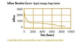
While it's important to know the peak flow (which usually becomes the design flow), it is equally important to know the intermediate and low flows of the system. A flow duration diagram (also called an exceedence curve) gives a good graphical representation of the duration and variation of flows. These diagrams will show flow as a percentage of time, arranged so that peak flows are at the extreme left and successively lower flows follow.
The station design flow is often equal to the peak flow. It's important to first view the station design flow as the peak capacity of the entire pump station, then determine how many, and what size pumps should be used. A very common design code requirement calls for installed spare (excess) pumping capacity to be equal to the output of one pump of the largest installed pumps.
When the design flow has been established, it's time to study the pipe system. We separate station piping from force-main piping because their requirements and impact on the system losses are very different. The station piping has to be laid out to fit the physical space available or allowed and must contain the necessary shutoff valves and check-valves. Head loss is often not a major issue, but must be calculated and included in the system head curve calculations. A velocity range of 3 to 8 fps can be used as good design guideline for the station piping.
The force-main is the common pipe leading from the pump station to the point of station discharge. It may vary in length, size, material and layout based on the project, the terrain, available excavation equipment and cost. This is an area where it is important to weigh the possible short-term benefits of a smaller diameter force-main (low up-front cost) against the long-term costs of higher energy consumption due to increased friction losses. Force-main velocities are often lower than the station piping velocity, and a range of 3 to 6 fps is recommended for the design flow.
In stations with multiple pumps, the actual operating velocities will generally be quite a bit lower because normal wastewater flows are typically only 1/4-1/2 of the design flow. This is not a problem as long as velocities below 1.5 fps are not sustained beyond a 24-hour period. In cases where this practice is questioned, force-main flushing is recommended, and can be accomplished automatically by running several pumps in parallel once a day.
About the Author:
Charles G. Stolberg is Executive Director of the Submersible Wastewater Pump Association (SWPA). For more information about the association or its programs and activities, visit the SWPA Web Site at www.swpa.org.

