Company Examines Slam Characteristics of Check Valves
By John V. Ballun
Check valve slam, whether it occurs as a minor nuisance or a building shaking thunderclap, warrants careful study and understanding. Characteristics of check valves have been extensively studied in Europe for many years. Only recently, check valve manufacturers in the United States have begun testing the dynamic characteristics of their valve designs and providing this data to design professionals. Val-Matic Valve and Mfg. Corp. has completed an exhaustive testing program on several types of basic check valves.
A methodology will be explained to use check valve response data and predict valve slam in any application. This is a tall order, but it's hoped that the methodology will be a sound starting point so that when combined with field experience over the coming years, a proven valve selection methodology can be adopted by the water and wastewater industries.
There are several technical papers, valve handbooks, and software design tools available to assist in check valve selection. The process is often difficult; selecting a check valve can involve many criteria from non-slamming characteristics, headloss characteristics, and operating costs, to installation laying length. Most of these criteria; however, are straightforward and can be calculated for the various types of check valves available.
It is a fact that given a severe pumping application, all basic check valves will slam. It is also a fact that in some applications no check valve will slam. It is the unpredictability of the middle ground between these extremes that makes the selection of check valves difficult.
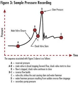
Check valve slam occurs after pump stoppage when the system flow reverses back towards the pump before the check valve is fully closed. The reverse flow causes the check valve to close rapidly through the remaining portion of its travel. The reverse flow is then stopped instantaneously by the closed valve causing a sometimes-loud water hammer in the pipe. The noise associated with the slam is not the impact of the disc into the seat, but rather the rapid stretching of the pipe due to the water hammer. Surprisingly, a resilient-seated check valve can make the same metallic slam sound as a metal-seated valve.
To prevent check valve slam, a check valve must either close very rapidly before appreciable reverse flow occurs, or very slowly once reverse-flow has developed. In order to close rapidly, studies indicate that:
• the disc should have low inertia and friction,
• the travel of the disc should be short, or
• the motion should be assisted with springs.
To close slowly, a check valve needs to be equipped with external devices such as oil dashpots and the pump must be capable of withstanding some backspin. Dashpot devices have proven to be effective, but are beyond the scope of this methodology. The answer to preventing check valve slam is not to find the fastest closing check valve and make it the "standard". Instead, the non-slam characteristics of the check valve must be matched with the pumping system. Every check valve has inherent advantages such as low cost, low headloss, or special flow characteristics. The best check valve is not necessarily the one with the least potential to slam.
To select a non-slam check valve, the pump station designer must first analyze the pumping system and calculate the deceleration of the liquid column after pump stoppage. Calculating the deceleration can be difficult because it's a function of many parameters such as pump inertia, length of the liquid column, friction losses in the piping system, and the static head or slope of the pipe. Engineers typically rely on a transient analysis of the system to compute deceleration.
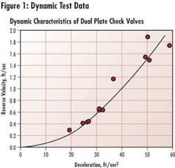
It is the responsibility of the valve manufacturer to provide the dynamic characteristics of their valves so that the engineer can predict the maximum reverse velocity that may occur. It's suggested that for each type of check valve, a response curve should be generated to show the relationship between the deceleration of the liquid column and the maximum reverse velocity through the check valve.
To develop dynamic characteristics for check valves, flow tests were conducted at the Val-Matic facility and the Utah Water Research Laboratory in Logan, UT. Several check valves were subjected to different initial forward flows and varying rates of flow reversals. (Figure 1.)
The test results for these valves are presented in Figure 3 together with similar data for swing check and ball check valves. The horizontal axis represents the deceleration of the piping system. The vertical axis is the maximum reverse velocity through the check valve. A single-pump, low-head system will have a deceleration of less than 20 ft/sec2. A high-head system of a multiple-pump system may have a deceleration as high as 40 ft/sec2. The reverse velocity can be converted directly into water hammer pressure using the basic relationship that every 1.0 ft/sec corresponds to a water hammer of 100 ft (43 psi).
The chart (Figure 3) was divided into three ranges: No Slam, Mild Slam, and Severe Slam. These divisions are based on numerous field observations of valve slams and acceptable levels of noise and disturbance to the valve and pumping system. Field experience has shown that water hammers in the range of 50 to 100 ft (or reverse velocities of 0.5 to 1.0 ft/sec) represent a mild slam and can be tolerated. Conversely, water hammers over 100 ft (or reverse velocities over 1.0 ft/sec) are extremely loud and should be avoided by either selecting a different check valve or modifying the check valve with heavier springs or hydraulic dashpots.
The results indicate that the best non-slam check valves offered by Val-Matic are the Dual Disc®-Check Valve (DDCV), Surgebuster® (SB), and the Silent Check Valve (SCV) which all feature spring-assisted closure. The next best non-slam check valves are the Swing-Flex® Check Valve (SFCV) and Tilted Disc® Check Valve (TDCV), which feature an angled seat and short stroke. (See Figure 2.) Finally, the valves with long strokes and no spring assist, the ball check and swing check, have the greatest potential for slamming.
The designer uses Figure 3 by finding the system deceleration on the horizontal axis and then reading the reverse velocity for the various types of check valves. For example, given a multiple pump station with a calculated system deceleration is 30 ft/sec2. (Figure 4.)
The designer can still consider using one of the valves in the "mild" or "severe" slam ranges by possibly changing to a speed-controlled pump or modifying the valve to include a stronger spring or an oil dashpot. At first glance that may seem impractical, but the characteristic low headloss of the Tilted Disc® Check Valve may be important for this application and an oil dashpot could be economically justified.
Finally, it is important to note some limitations of using the dynamic characteristic data. First, the test data is based on installation in a horizontal pipeline. Some valves rely on gravity to accelerate disc closure such as the Swing, TDCV, and SFCV valves and when installed in a vertical pipe, may have a greater tendency to slam. Conversely, other valves such as the DDCV and the SCV will close faster in a vertical line due to gravity effects on their discs and have a lesser tendency to slam. Also, the dynamic characteristics of the valve are dependent on valve size but no data is available at this time to predict the exact effect of size. Larger valves have heavier discs and longer strokes and will likely produce somewhat higher reverse velocities. The manufacturer should be consulted for the potential impact of orientation and size on the performance of the selected valve.
It should be clear that dynamic characteristic data for check valves only offers the designer the tools necessary to evaluate the non-slam characteristics of various check valves. This information, combined with other readily available valve characteristics such as headloss, laying length, waterway design for fluids containing solids, and cost will provide the designer with all of the tools necessary to make reliable valve selections.
About the Author:
John Ballun is a registered P.E. and holds several patents in the valve industry. He serves on six of the AWWA Standards Committees and also serves on five committees for the Manufacturers Standardization Society. 630-941-7600.


