Company Turns to Rainwater Harvesting for Flushing, Cooling
By Brendan Bates
The demand for water harvesting systems is expected to increase as municipalities, homeowners, business owners, commercial and industrial building owners realize the benefit of capturing, storing, filtering and using harvested rainwater for such purposes as flushing plumbing fixtures, irrigating parks and fields, vehicle washing and mechanical make-up feed water for industrial processes.
Water harvesting systems can help reduce water bills and alleviate demand on municipal systems but more importantly they reduce demand on limited potable water supplies.
Layout of the rainwater harvesting system at HP Critical Facilities Services in Chicago.
Metropolitan Industries, Romeoville, IL, designs and manufactures these systems for the commercial, municipal and industrial markets. The company recently worked with engineer Mark Nykowski of HP Critical Facilities Services in Chicago to develop a rainwater harvesting system that would be used as a pressurized source of water for flushing plumbing fixtures, as well as an emergency source of water for the facility's cooling tower make-up demand.
How It Works
In a typical rainwater harvesting system, a "Harvest-Zone" is designated. In this case, the harvest-zone was the rooftop of the facility. The rainwater is collected via the roof-drain system, and eventually flows into four underground reservoirs. Each of the reservoirs has a gross storage capacity of 40,000 gallons, for a total gross storage capacity of 160,000 gallons.
The underground storage reservoirs are installed using an interconnecting piping arrangement that allows the reservoirs to store equal amounts of water, and allows all of the water to flow toward a Metropolitan factory-prefabricated Underground Rainwater Pressurization Station.
The pressurization station is designed to collect the gravity-flow from the underground reservoirs, and direct water through two "Aspiration Units", which reduce the particulate matter in the water down to 20 microns before being pumped. The station includes two variable-speed submersible pumps, each designed to pressurize the rainwater at a peak flow rate of 80 gpm, with a target output-pressure of 80 psi, with a combined peak flow of 160 gpm.
The station is designed to allow the aspiration units and pumps to be removed for maintenance, inspection, and repair from grade elevation, without the need to drain the reservoirs or station. It also prevents the need for personnel to enter the confined-space of the station's wet-well.
One of the station's other unique features, which sets this design apart from other typical rainwater-harvesting system designs, is an integral Dry-Well chamber, adjacent to the wet well. This chamber is designed to encase the discharge piping of the station, as well as the isolation valves, silent check valves, and pressure monitoring gear. This chamber is much shallower than the wet-well, and is designed to allow personnel to enter.
Once the pressurized rainwater exits the pressurization station, the water travels below grade and enters a mechanical room which houses a Metropolitan factory-prefabricated Rainwater Treatment Station.
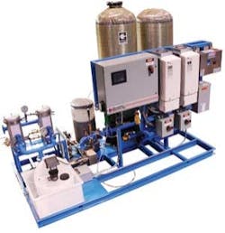
The rainwater-treatment station is a complex fabrication which must allow for aeration of the water in the underground storage reservoirs. It also controls and operates the pumps in the underground pressurization station, as well as performs critical functions to ensure the safe re-use of the harvested rainwater. The treatment station filters, disinfects, recirculates, and colorizes the water.
The treatment station includes a programmable logic control center, pressure transducers, flow meter and variable frequency drives (VFDs), which operate in unison to control the flow and pressure of the water from the pressurization station. Once the rainwater enters the treatment station, the flow path first takes the water through a pair of redundant cartridge filters, which further reduce the particulate matter down to the size of 5 microns, before allowing the water to flow into the system's ultraviolet disinfection unit. This filtering is critical to the effectiveness of the UV treatment, as larger particle sizes may tend to allow "shadowing" of other particles, thus rendering the UV treatment less effective.
The rainwater treatment station filters, disinfects, recirculates, and colorizes the water.
Upon exiting the UV chamber, a precisely measured portion of the water flow is allowed to flow through a recirculation port, which is routed to an aeration device in a predetermined point in the arrangement of underground storage reservoirs. This measured flow is critical in ensuring that the stored water does not become anaerobic.
Next the water is injected with a metered quantity of calcium hypochlorite, which not only provides additional disinfection beyond the UV treatment, but also allows residual disinfection of the water for extended periods of time.
Finally, prior to leaving the treatment system on the way to the intended service, the filtered, disinfected water is injected with blue food-grade dye. The dye is added to provide instant identification of secondary water, to ensure that any cross-connection with fresh water supplies within the facility is avoided.
About the Author: Brendan Bates is a System Engineer with Metropolitan Industries, a single-source supplier of pumps, control systems and ancillary equipment for the water and wastewater industry. The company specializes in packaging pump systems. All systems come complete with UL listed controls and are manufactured in-house.Past IWW Issues


