Guide to Selecting Sealless Thermoplastic Pumps By Kenneth Comerford

by Kenneth Comerford
(Editor’s note: This is the second article in a two part series examining sealless pump technologies. The first in the series appeared in the July/August issue of Industrial WaterWorld.)
The selection of the ideal sealless thermoplastic pump for a particular application requires a thorough awareness of the application requirements, including the ability of the pump to handle the required flow and differential pressure, and what materials will perform reliably in the service.
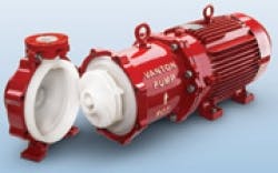
This magnetic-drive, close-coupled pump is shown with wet end opened and the solid, molded-thermoplastic casing, impeller and bearing housing exposed.
The following article examines the various types of sealless pumps available on the market, their design characteristics, and things to consider for specific applications.
Magnetic-Drive Pumps
In magnetic-drive pumps, the casing is a pressure-containment component whose strength is a significant characteristic. Mechanical strength is also an important factor to consider when determining the flange loading that can be carried by the pump. MDPs are available with metal casings that are lined with thermoplastics or constructed of fiberglass-reinforced thermoset resins and solid, molded thermoplastics. Some solid thermoplastic designs also incorporate cast-iron structural supports to provide enhanced pressure-containing and nozzle-load capabilities that match those of metal pumps meeting ANSI process-pump standards.
When considering the use of metal casings lined with corrosion-resistant thermoplastics, special consideration of the service conditions is critical. The following questions should be addressed when selecting the special material: How will the lining hold up under the flow conditions? How abrasion-resistant is the lining material? How significant is the danger of wear or pinholing, which might lead to corrosion of the metal or contamination of the product? These concerns become less significant as lining thickness increases, or with designs that use thick-sectioned, replaceable wet-end components.
Driven shaft: This component features a stainless steel or high-alloy shaft that is completely encapsulated, or sleeved, in a chemically inert, nonmetallic material, such as polypropylene (PP) or polyvinylidene fluoride (PVDF). This design provides strength, and allows one to select the thermoplastic material based on the required corrosion resistance to the chemicals being pumped.
Bearing carrier or housing: This structural component houses the wet-end bearings. The bearing housing features either solid thermoplastic construction or a plastic-lined metal component.
Containment shell (the can): The containment shell, like the casing, must withstand high pressure. Its material of construction is selected according to the required corrosion resistance and mechanical strength. Most nonmetallic MDPs use a two-layer can, whereby the inside can – the one in contact with the corrosive fluid – is made from chemically inert fluoropolymers. The outer can, which is not in contact with the aggressive fluid, and mainly provides mechanical strength, is generally constructed of fiber-reinforced-plastic or of metal.
Driven magnet: The inner magnet is constructed of rare-earth metals such as samarium cobalt or neodymium. To provide the chemical resistance required, these magnets are completely encapsulated with PTFE, PVDF or PP.
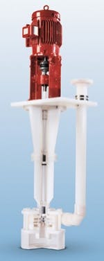
Wet-Pit Vertical Sump Pump
These chemical pumps, intended for corrosive services, are available in PP, polyvinyl chloride (PVC), chlorinated polyvinyl chloride (CPVC), PVDF and fiberglass-reinforced plastic (FRP). Wetted parts of the pump assembly consist of the portion of the pump shaft situated below the pump mounting plate (also called a coverplate), the shaft sleeve bearings, the casing, the impeller and the pump column, which structurally supports the immersed casing and shaft.
Typically, the motor mounts above the mounting plate. In cantilevered designs, which are recommended for use where dry running may occur or where acceptable wet-bearing lubrication is not attainable, the pump shaft is supported by anti-friction bearings above the mounting plate. There are no bearings immersed in the fluid. These pumps are limited to sump depths of approximately 5 feet, but with tail pipes they can effectively be used in slightly deeper sumps.
Shaft configurations: In wet-bearing designs, the shaft is supported from above the mounting plate using antifriction, grease-lubricated bearings in the pedestal, and is additionally supported from below the mounting plate with product-lubricated sleeve bearings. The choice for the outer bearings includes ceramic, silicon carbide, siliconized carbide, carbon-filled PTFE and glass-filled PTFE. For extreme conditions, the shaft journals (or inner bearings) are constructed of ceramic materials. Wet bearing designs tap fluid from the pump discharge and route it to each bearing, since the upper wet bearings are not flooded when the liquid level is low. When the pumped fluid contains solid particles that can damage the wet bearings, an independent clean-water flush must be used.
In cantilevered designs, the shaft is supported from above the mounting plate, requiring heavy-duty antifriction bearings that can carry the larger loads. The shaft must also be of sufficient diameter to minimize shaft deflection.
Corrosion and potential metal contamination of the fluid can be prevented by constructing the shaft of Type 300 Series stainless steel, and sleeving the shaft with a thick-walled thermoplastic material.
Flexible-Tube Pumps
Flexible-tube or flexible-hose pumps handle slurries, high-viscosity fluids and abrasives, can be run dry, and have excellent self-priming capabilities. Pulsations are present in the discharge line due to the nature of the pumping mechanism.
Pump head: The pump head contains the tubing, the roller or shoe-drive assembly that traps the liquid in the tube, and the casing that houses these components. The rollers or shoes trap the liquid between the squeeze points. Since the corrosive liquid does not contact the head under normal operating conditions, the head on larger industrial units is usually constructed from cast-metal components. Heads of smaller, lighter-duty units may be constructed of rigid plastic. Duplex systems, in which two heads use one drive, provide higher flows and reduced pressure pulsations.
Tubing: A variety of elastomeric materials, including polyurethane, chlorosulfonated polyethylene, and nitrile, butyl and natural rubber, are available for tubing construction.
The service life of a flexible tube pump is highly dependent on the specific material selected for the tubing. Since the pumped fluid is totally contained inside the tubing, the fatigue life and the maximum pressure of these pumps are dictated by the material characteristics and the fluids being pumped. Flexible tube pump hoses undergo many cycles of compressive and tensile stress.
Drive: Most flexible-hose pumps operate at a shaft speed below the motor’s synchronous speed. This is achieved by employing reducing gears or a variable-speed drive. The use of a variable-speed drive permits the pump flowrate to be varied so that specific metering requirements are met. This also helps extend the fatigue life of the tube.
Flexible-Liner Pumps
Flexible-liner pumps are available in close-coupled configurations with a C-face motor, and frame-mounted designs coupled to a foot-mounted, horizontal motor. These units are self-priming, can be run dry, and can dependably handle slurries and viscous liquids. Like flexible-tube pumps, flexible-liner pumps also tend to produce pressure pulsations. At selected speeds, however, the pumping action is gentle enough to prevent the settling out of suspensions and provide for the effective handling of latex emulsions and similar materials. Duplex designs are available for higher flows and for reducing the pulsation tendency.
Flexible-liner pumps operate at 1,800 rpm or less and are available with variable-speed drives and can be operated at zero flow for short periods of time. However, the differential pressure should not exceed 30 PSI for continuous service on most sizes. The major components consist of the liner, body block, rotating assembly, cover plate and bearing frame.
The two components for which material selection is critical are the body block and the liner. These are the only components in contact with the fluid.
Rotating assembly: The rotating assembly of the flexible-liner pump consists of an eccentric rotor that is mounted on an overhung, frame-mounted shaft, and is completely isolated from the pumped fluid. The liner acts as a joint gasket between the pump body and cover plate, and between the body and the bearing frame. Since the aggressive fluid does not contact the rotor, the rotor does not require special materials of construction. As the rotor oscillates within the liner, it creates a sealed, rolling contact point between the inside surface of the body block and outer surface of the liner. This imparts a progressive squeegee action on the trapped fluid.
Body block: The body block contains the suction and discharge nozzles, and is considered to be the pump casing. Constructed from rigid thermoplastics, the body block is sandwiched between the two external flanges of the liner, which act as gaskets. The interior surface of the bore is in direct contact with the fluid, making material selection critical. Standard units provide a choice of ultra high-molecular-weight polyethylene (UHMWPE), PP and PTFE.
Flexible liner: The liner is a thick-walled, molded elastomeric component that can readily be replaced in the field without the use of special tools. Only the outside circumference of the rugged unit is in contact with the pumped fluid. Its cross section forms an “H” pattern – the vertical legs of the “H” act as static gaskets between the body block, the cover plate and the bearing frame. It is this feature that makes the flexible-liner pump a “sealless” pump. The flanges on this liner are pressed to the sides of the body block by concentric grooves on the pedestal assembly and cover plate, isolating the fluid within the formed channel.
The wide choice of liner materials available, and the ease with which liners can be changed, makes it economically feasible to use a single flexible-liner pump for numerous applications.
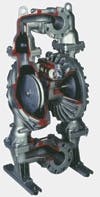
Diaphragm Pumps
Controlled-volume diaphragm pumps are widely used for viscous liquids, abrasive slurries, shear-sensitive liquids (such as paint) and fluids containing small, suspended solids. The diaphragm’s relatively low oscillation frequency and low velocity are gentle on the fluid being pumped.
The air-operated, duplex nonmetallic pump is the type most widely used in the CPI. This configuration features two diaphragms linked by a common shaft. The suction stroke that draws pumped liquid into the pumping chamber doubles as the discharge stroke on the opposing diaphragm, which expels liquid out of that pumping changer. Like many positive-displacement pumps, the diaphragm pump has a pulsating discharge pressure.
Diaphragm pumps are self-priming, and can be run dry. The major components of the wet-end assembly include the body, diaphragm, and suction and discharge check valves and valve seats.
Body: The body of the controlled-volume diaphragm pump is the pump casing. The joint between the body and the diaphragm separates the wet-end pumping chamber from the mechanical power end. Materials of construction for this component include PP, PVDF and PTFE.
Diaphragm: The flexing of this elastomeric component is responsible for the pumping action. The material of construction for this critical component should be selected on the basis of its resistance to the aggressive fluid that is being handled. Options include neoprene, polyurethane, PTFE, Buna-N, EPDM, fluoropolymers, and chlorosulfonated PE.
Check valves: Check valves control the flow of liquid into and out of the pumping chamber, and are exposed to the corrosive pumped liquid. Materials of construction are similar to those used for the diaphragm. There is one check valve at the inlet and one at the exhaust of each liquid pumping chamber.
Check-valve seats: During the discharge stroke of the diaphragm, the check valve at the inlet of the pumping chamber is pushed against the seat at the pumping-chamber inlet. Likewise, during the suction stroke, the check valve at the discharge end of the pumping chamber is pushed against the seat at the respective location. Since the check-valve seats are exposed to the pumped fluid, they must be chemically resistant. They can be supplied in the same variety of elastomers as the diaphragm.
The selection process
The selection of the ideal sealless thermoplastic pump for a particular application requires a thorough awareness of the application requirements, including the ability of the pump to handle the required flow and differential pressure, and what materials will perform reliably in the service. When selecting a material of construction, three criteria are used to simplify the choice of a specific thermoplastic: The maximum fluid temperature, the desired abrasion resistance of the pump and the chemical inertness of the pump material to the process fluid.
The final thermoplastic material choice will depend on such factors as solids-handling and dry-run capabilities, space requirements, initial cost, maintenance costs, commercial availability and service experience with the product and vendor.
About the Author: Ken Comerford is Vice President, Vanton Pump and Equipment Corp. Since joining the company in 1982, he has served in a variety of roles including Sales and Marketing Manager. He was promoted to Vice President in 2006, and currently sits on the board of directors and is a member of the Water Environment Association.