Cooling Tower Blowdown Treatment Using an Inclined Plate Clarifier
by Mohamed Ahmed Salah, P.Eng.
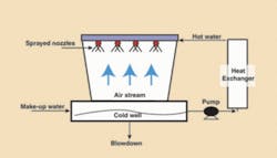
The primary use of cooling towers is to remove heat absorbed in circulating cooling water systems used in refineries, power plants, petrochemical plants and other industrial facilities. Cooling towers represent a relatively inexpensive and dependable means of removing low-grade heat from cooling water. They’re evaporative coolers that cool water to near ambient temperature. Heat is dissipated through the natural process of evaporation that takes place when air and water are brought into direct contact in the cooling tower.

The thermal efficiency and proper operation of the cooling tower all depend on the quality of the make-up water, water treatment and blowdown rate. Make-up water is used to replenish water lost to evaporation, blowdown and drift. Drift (or windage) is the term for water droplets of the process flow allowed to escape in the cooling tower discharge. Unlike steam generating boilers, the quality of the make-up water for cooling tower isn’t required to be very high. Total suspended solids (TSS) as high as 10 mg/L may sometimes be acceptable.
Cooling Tower Solids
The water of evaporation exits the tower in a pure vapor state leaving behind its burden of total dissolved solids (TDS) and TSS to concentrate in the recirculating mass of water. Given no control, the TDS level in the circulating water will increase tremendously, jeopardizing not only the cooling tower but the heat exchangers and all other water circuit related components as well. Also, cooling towers make excellent air scrubbers/washers. Due to the high volume of air passed through cooling towers, most contaminants in the air end up in the cooling water basin. Some of those contaminants are dirt, grit, sand, slime and algae. Other sources that contribute solids in the cooling tower include chemical residues and calcium scale flake off. Chemical addition is made for the purpose of corrosion protection, microbiological control, and to increase the solubility of mineral salts.
Solid contaminants can clog cooling tower spray nozzles resulting in poor water distribution through the fill. Most countercurrent cooling towers use pressurized spray distribution systems. The spray nozzles often have small orifices that are easily clogged. Also, deposits on heat transfer surfaces increase the fouling factor that significantly decreases transfer efficiency.
To maintain efficient cooling tower operation, solid contaminant levels have to be reduced. One way to do that is to bleed off (blowdown) a portion of the re-circulating water on a regular basis. Figure 1 shows a typical cooling tower recirculation loop with blowdown. Solids content of the blowdown may vary from 20-300 mg/L depending on the make-up water source used and the frequency of blowdown. TSS spikes as high as 1,000 mg/L are reported by some power plants. Higher suspended solids are also expected in geographical areas like the Middle East or African Sahara that experience seasonal sand storms.
Inclined Plate Clarifier
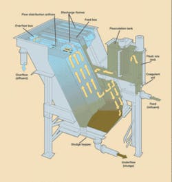
To minimize waste, the cooling tower blowdown can best be treated using an inclined plate clarifier such as the Lamella® Gravity Settler (LGS) manufactured by Parkson Corp. This clarifier (see Figure 2) is an inclined plate, shallow depth sedimentation unit. It performs the same function as a conventional clarifier, but occupies only a tenth of the space.

A typical inclined plate clarifier of this type is 2' or 4'wide by 10' long, spaced 2" from adjacent plates, and inclined at an angle of 55°. The plate length is divided into two sections, one above and below the feed point. The section above is called “clarification area” and is used in sizing the unit based on overflow loading rate. The section below the feed point is called “thickening area” and is used to pre-thicken the sludge before it enters the hopper. Common split for free settling applications is 80% clarification area and 20% thickening area. The clarifier often comes with integral rapid mixing and flocculation chambers and mixers. Standard materials of construction for a package LGS is carbon steel for the tank, and fiberglass-reinforced plastic (FRP) plates with polyvinyl chloride (PVC) stiffeners that support the plates. The construction materials of the tank and plates can sometimes vary based on water composition, pH and temperature. In most applications, the above standard materials resist corrosion. Only the FRP plates need to be replaced after maybe 20-25 years of operation.
Uniform flow distribution is attained by designing for a small pressure drop at the discharge of each plate. Separate orifices for each plate ensure uniform pressure drop over each plate and thus equal flow through the unit. Orifice sizes range from about ½"-1" diameter, and the expected pressure drop is between 2"-4" of water column. This pressure drop controls flow by creating the same hydraulic conditions above each plate. Sludge re-entrainment is avoided by the fact that settling and thickening occur below the influent of each plate.
Process Flow Sheet
Figure 3 shows the process flow diagram of a complete plant for suspended solids blowdown treatment process. Blowdown water laden with suspended solids enters into a rapid mixing chamber where about 1-2 ppm polymer is added. To obtain the best results, the polymer solution is often diluted with water to 0.2-0.5%. Then, the flocculation chamber equipped with variable speed drive gently mixes the chemically treated water to produce settleable floc particles. The flocculated water enters at the side of the plates and clear effluent discharges at the top. Solids slide down the plates and drop into a quiescent sludge hopper. The three streams do not interfere with one another.
Once the effluent is collected in the effluent flume, it discharges from the unit. Typical solids removal efficiency is 80-90% of solids. The treated effluent can either be discharged to a municipal sewer line or further treated to recycle to the cooling tower.
The underflow from the LGS, which has 1-4% total solids, is sent to a sludge holding tank. Either air operated diaphragm (AOD) pumps or positive displacement pumps can be used for pumping the sludge. Since there could be a wide variation of influent TSS, sludge recycle may become necessary to increase the concentration of suspended solids in the feed for good flocculation conditions. If this is the case, the sludge return should be pumped into the feed stream before it enters the flash mix tank and/or polymer injection.
A plate-and-frame filter press is used to dewater the sludge. The detailed operation of the filter press is beyond the scope of this article. The filter press consists of a series of individual filter plates held firmly together during operation. Each plate is covered with filter cloth, which serves as a platform for development of the filter cake. As sludge is pumped in, a cake of solids begins to build on the cloth. The filtrate from the filter press, which passes through the cloth, can be returned to the Lamella Gravity Settler and the sludge cake hauled out for disposal.
About the Author: Mohamed Ahmed Salah is a registered professional engineer. He wrote this article as applications engineering manager for Parkson Corp., of Fort Lauderdale, FL. Contact: 800-553-5419 or www.parkson.com