A Reliable Technology for Production of Pyrogen-Free Water
by Peter Wirz and Christian Stark
Up to a few years ago, the European Pharmacopoeia still insisted pyrogen-free water be produced by distillation. The American and Japanese Pharmacopoeias both permitted preparation of WFI (Water for Injection) using more modern and cost-saving membrane technology in use for about two decades. Under pressure from the biopharmaceutical industry, the European Pharmacopoeia recently created a new compendium determining water quality of HPW (Highly Purified Water).
Overview
Various membrane configurations are available on the market, such as:

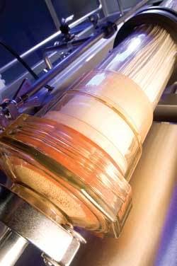
Figure 3. Ultrafiltration Plant in Hot Operation (Capacity: 50 m3/h)Click here to enlarge image Looking at the various membrane processes in Table 1, it’s obvious RO shows the lowest molecular weight cut-off (MWCO). In general, RO membranes achieve excellent separation of salts, microorganisms and pyrogens. The structure of the module, though, shows some mechanical weak points that aren’t acceptable for “sterile and pyrogen filtration.” In the case of spiral wound elements, these are the high number of sealings, macropores frequently present in the membrane and faulty points of glued ends of the rolled packet. All these small porosities, insignificant for demineralization purposes, can lead to passages for microorganisms and pyrogens. Such shortcomings aren’t present in hollow-fiber UF modules, which are therefore ideal for production of water of HPW or WFI quality.UF membranes with their asymmetrical membrane structure have no dirt adsorption capacity whatsoever and, in such applications, are typically operated in crossflow mode, i.e., there must always be a flow across the membrane surface which washes out separated material. A UF plant used, for example, for pharmaceutical applications, will thus always produce concentrate as well as filtrate - or permeate.
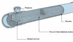
Figure 1. The Hollow-fiber ModuleClick here to enlarge image Since fully demineralized water, as it usually circulates in the network of a pharmaceutical facility, often shows a considerable load of microorganisms and organic material, a UF plant must operate with a comparatively high crossflow rate over the membrane, i.e., the concentrate is recirculated. Further, in most cases, backflushing cycles are scheduled during which the filtrate flows through the membrane in the opposite direction to remove deposited material, which then is discharged with the concentrate.Such backflushing cycles which, depending on the quality of the demineralized water feed, can be necessary in intervals of only few minutes, use only a fraction of filtrate produced; therefore, filtrate production doesn’t need to be interrupted. This is done typically by splitting the plant into two or three lines, with one producing backflush water for another over a short period of time, 15-40 seconds.Module StructureWhich characteristics are required on the UF modules?Accurate MWCO No short-circuit flow between filtrate and feed water High continuous temperature operation (80°C) Hot water sanitizable (90°C) and, preferably, steam sterilizable (121°C) Deadspace-free structure (rinsing behavior)* Integrity testing capabilities Complete water removal capabilities * No hold-up area where water can sit stagnant.
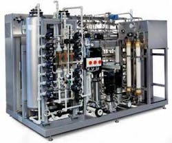
Figure 4. Ultrafiltration System (Capacity 4.5 m3/h)Click here to enlarge image For the hollow-fiber configuration (see Figure 1), fiber ends are potted in an epoxy block. Since the epoxy resin extends to the permeate outlet, this design has little or no deadspace. O-rings, lip seals, glued and welded joints, which all present a leakage risk, are thus avoided by simple means.Hollow-fiber modules are available with MWCO limits of less than 6,000 Daltons, which is far below the size of pyrogens. The modules discussed here also are structured as double asymmetrical membranes. With two discrete layers, a short-circuit is virtually impossible, ensuring maximum safety.
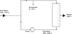
Figure 2. Ultrafiltration System (Diagram) Click here to enlarge image To validate the tightness of the module, an integrity test may be installed in UF plants that can be triggered by a key in the control cabinet. In this verification (pinhole test), the water is emptied from the concentrate side of the modules to apply sterile compressed air. If a fiber is broken, this is visible by rising air bubbles on the filtrate side. With this simple method, the smallest lesions of the fibers can be discerned by formation of clearly visible air bubbles.
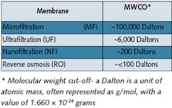
Table 1. Membrane performance comparisonClick here to enlarge image Since the module housings can be transparent, small leakages can thus be detected. This integrity test is more accurate than an endotoxin determination, which might miss these due to high dilution measurements.
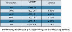
Table 2. Module Capacities at Various Temperatures*Click here to enlarge image The high separation reliability of such hollow-fiber modules was impressively demonstrated in a challenge test (for retention of bacteria) executed with Messrs Sanofi-Aventis, former Hoechst Ltd, in Frankfurt, Germany. A living culture of over 107 Pseudomonas diminuta per milliliter was continuously recirculated from a container over a hollow-fiber lab module for two weeks. Produced filtrate was fed in its entirety to a sterile filter with a membrane, which was removed once a day and incubated. Only once - before starting the test - the system was sterilized with saturated steam at 121°C from the UF module up to and including the sterile membrane. During the test phase, the module was loaded with approximately 1013 to 1014 microorganisms. The result didn’t show a single microorganism of the species P. diminuta in the filtrate.Ceramic vs. PolymericCeramic modules, which are an alternative to polymeric modules, show an MWCO of approximately 15,000 Daltons. Ceramics are much more resistant to aggressive chemicals and high temperature than polymerics and, based on these reasons, are mainly applied in wastewater and/or effluent treatment.Susceptibility to breakage during steam sterilization, the need for seals as well as the surface roughness are, however, characteristics that call into question use of this module material in pharmaceutical applications. Likewise, the rather simple pinhole test cannot be executed without problems since air molecules pass through ceramics and thus make this verification impossible.UF System OperationA UF system can supply its filtrate in various ways. The first is into a storage tank from where the pyrogen-free water is transferred through a distribution system to points of use by booster pumps. Nowadays, this concept is often used for skid-mounted compact water systems containing pre-treatment, demineralization and UF processes on a single skid. A second possibility is to take the filtrate directly at the outlet of the UF plant and feed it into the distribution system by means of a pump operated in-line (see Figure 2). Both possibilities have strengths and weaknesses.Production into a tank:Greater flexibility in production Usually smaller capacity and lower investment costs required (tank acts as buffer) Disinfection (e.g., by ozone) of the tank and distribution system or hot storage (>65°C) are necessary Production directly into a distribution system:Layout of the plant for peak capacity (plus recirculation flow) Booster pump required downstream of the UF Loss of production capacity during backflushing Continuous disinfection (e.g., by ozone), not necessarily required in the distribution system Continuous cleaning of the water in circulation Higher security against secondary contamination (e.g., by taps) A further possibility is hot operation of a UF plant (see Figure 3). The temperature, aside from quality of the feed water, has a positive influence on operating behavior (fouling rate) of the membranes.Hot operation (65-85°C) offers some advantages over cold production:Constant module capacity (lower tendency of fouling) Backflushing needed only sporadically Longer production cycles between steam sterilizations With hot storage, no further microorganism-reducing processes (e.g., with ozone) needed
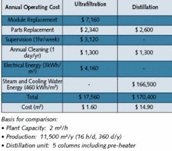
Table 3. Cost Comparison - UF vs DistillationClick here to enlarge image UF vs. RO
In principle, RO also presents an alternative with its lower MWCO in comparison to UF. TDS reduction via RO makes a second pass common in pharmaceutical applications more pragmatic for a UF system.The spiral wound RO configuration because of its O-rings, lip seals and glue lines presents a potential problem with microorganism passage, which may require alternate disinfection, e.g., ozone.Most RO modules are, contrary to UF, not steam-sterilizable and show a considerably inferior rinsing behavior, e.g., potentially retain some stagnant water. Still, there are spiral wound RO membranes, as well as spiral wound UF membranes, that can be sanitized with hot water.ConclusionThe largest quantities of WFI quality water, e.g., sterile and pyrogen-free, are needed for all kinds of rinsing purposes. Depending on pharmacopeia (U.S., European or Japanese) requirements, WFI quality water is prescribed, e.g., for the final rinsing of vessels for parenterals, or pharmaceutical products. It’s also prescribed in the final steps of active substance production for parenteral (ingestible) applications, however, without a production method stipulated.The role of ultrafiltration (see Figure 4) for the production of WFI (though allowed by the U.S. and Japanese pharmacopeias) isn’t predominant because, in almost all cases, this demand is already satisfied by existing validated distillation plants.Hollow-fiber UF advantages include reliability, integrity test, steam sterilizable and operating cost. From small capacities of 500 L/h, UF is an extremely economical process and a reliable alternative to classic distillation. For larger capacities, the cost savings multiply due to low energy cost. A comparison between a UF and distillation plant shows this clearly (see Table 3).UF operating results show that sterile and pyrogen-free quality water is ensured over months and years. UF plants are sterilized with saturated steam at 121°C in regular intervals. This is usually done to clean the membranes only and not to ensure filtrate sterility. Therefore, ultrafiltration is the method of choice for large quantities of WFI quality water. About the Authors: Peter Wirz and Christian Stark work for Christ Water Technology Group in Aesch, Switzerland. Christ’s U.S. offices, Tenergy Christ Waters LLC, are based in New Britain, CT. Contact: [email protected] or www.christwater.com
In principle, RO also presents an alternative with its lower MWCO in comparison to UF. TDS reduction via RO makes a second pass common in pharmaceutical applications more pragmatic for a UF system.The spiral wound RO configuration because of its O-rings, lip seals and glue lines presents a potential problem with microorganism passage, which may require alternate disinfection, e.g., ozone.Most RO modules are, contrary to UF, not steam-sterilizable and show a considerably inferior rinsing behavior, e.g., potentially retain some stagnant water. Still, there are spiral wound RO membranes, as well as spiral wound UF membranes, that can be sanitized with hot water.ConclusionThe largest quantities of WFI quality water, e.g., sterile and pyrogen-free, are needed for all kinds of rinsing purposes. Depending on pharmacopeia (U.S., European or Japanese) requirements, WFI quality water is prescribed, e.g., for the final rinsing of vessels for parenterals, or pharmaceutical products. It’s also prescribed in the final steps of active substance production for parenteral (ingestible) applications, however, without a production method stipulated.The role of ultrafiltration (see Figure 4) for the production of WFI (though allowed by the U.S. and Japanese pharmacopeias) isn’t predominant because, in almost all cases, this demand is already satisfied by existing validated distillation plants.Hollow-fiber UF advantages include reliability, integrity test, steam sterilizable and operating cost. From small capacities of 500 L/h, UF is an extremely economical process and a reliable alternative to classic distillation. For larger capacities, the cost savings multiply due to low energy cost. A comparison between a UF and distillation plant shows this clearly (see Table 3).UF operating results show that sterile and pyrogen-free quality water is ensured over months and years. UF plants are sterilized with saturated steam at 121°C in regular intervals. This is usually done to clean the membranes only and not to ensure filtrate sterility. Therefore, ultrafiltration is the method of choice for large quantities of WFI quality water. About the Authors: Peter Wirz and Christian Stark work for Christ Water Technology Group in Aesch, Switzerland. Christ’s U.S. offices, Tenergy Christ Waters LLC, are based in New Britain, CT. Contact: [email protected] or www.christwater.com