Micro- or Ultrafiltration and Reverse Osmosis: A Popular Combination for Industrial Treatment
By Brad Buecker
The shale gas revolution is leading to rapid transition from coal to natural gas in the power industry and also to significant expansion of other industries including petrochemicals. Many of these plants require high-purity water for steam generation and other unit operations. In addition, plant personnel are facing tighter guidelines on wastewater discharge quality and quantity.
Membrane technologies have been leading the way with regard to makeup water treatment, and they are emerging as core components of wastewater treatment systems. This article examines direct applications of these technologies and includes several lessons learned.
Membranes for Makeup Water Pretreatment
For years, clarification followed by media filtration was the common technique for removing suspended solids from makeup water. And indeed, modern clarifiers may still be quite appropriate in many situations, particularly where lime softening is needed. When suspended solid removal is the primary goal, the membrane techniques of micro- and ultrafiltration (MF and UF, respectively) have attracted much interest. These technologies are typically much less labor- and chemical-intensive than clarifiers.
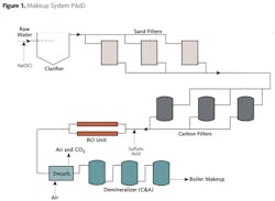
At one of my former plants, the makeup water flow treatment scheme for the facility's 800 MW supercritical boiler was formerly arranged as illustrated in Figure 1.
This system operated for many years, with the reverse osmosis (RO) being added in the mid-1980s and the forced-draft decarbonator in the late 1990s. Table 1 outlines a typical analysis of the lake water that feeds the makeup system, where the normal turbidity level of the lake water ranges from 5 to 15 nephelometric turbidity units (NTU).
By the early 2000s, the clarifier was nearly 30 years old and was beginning to show its age. When the clarifier operated properly, effluent turbidity could be lowered to 0.3 NTU, but upsets in lake water chemistry and/or the equipment itself often caused excursions in clarifier performance, such that effluent turbidities sometimes exceeded 1.0 NTU. In these cases, the chemistry staff would see quick fouling of RO cartridge and bag pre- filters and an increase in RO membrane differential pressures. Also, the clarifier itself was quite maintenance-intensive and consumed significant amounts of expensive coagulants and flocculants.
In autumn 2004, based on reliable information from colleagues within the power industry, we tested (and subsequently installed) a microfilter (MF) in the makeup water system to ascertain if it would produce cleaner water than the clarifier/sand filters for RO feed and how this would, in turn, affect downstream equipment. Whereas most RO systems utilize spiral-wound membranes, microfilter membranes are of a hollow- fiber configuration, in which each module contains thousands of spaghetti-sized membranes (see Fig. 2).
To produce the 300-gpm flow required by the steam generator and its auxiliary systems, 24 membrane modules were necessary (see Fig. 3).
The microfilter process operates in what may be accurately termed a combination dead-end/cross-flow method, in which the raw water flows parallel to the membrane surface (crossflow), but the particles accumulate on the membrane surface (dead-end).
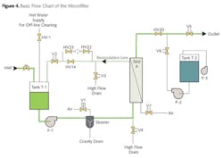
Typically, around 95 percent of the water exits as permeate with 5 percent reject. The membranes in this design are configured in a way that the raw water flows from outside to in, with the reject passing along the outside surface of the fibers. The basic water flow path is outlined in Figure 4.
Per an operator-adjustable automatic timer (normal frequency every 20 minutes), filtration halts, and pump P-2 activates to backwash the membranes of accumulated particles. The process then resumes.
This system has operated extremely well for over eight years with not one failure of the 140,000-plus membranes, and it consistently produces water with a turbidity of less than 0.04 NTU. An important lesson learned is that a chemical cleaning is required every one or two months. Otherwise, particles and foulants will embed within the membranes and become difficult to remove. A common procedure utilizes a warm caustic/bleach flush to remove organic and microbiological materials followed by a rinse and a citric acid cleaning to remove iron particulates. Most of today's units include an automatic cleaning system to minimize operator attention.
The Next Step: Reverse Osmosis
Reverse osmosis has become the primary demineralization process for many makeup systems, but reliable operation requires knowledge of the process. The typical industrial RO unit does not utilize hollow-fiber membranes but rather spiral-wound elements. "They are, in essence, jelly-roll formations of RO membranes sandwiching fabric spacers and sealed on three sides. The fourth, open side is sealed around the perforations of a center core, usually of PVC."1 It is this feature of RO that has made micro- and ultrafiltration so attractive for pretreatment, as the nearly complete removal of suspended solids greatly minimizes mechanical fouling of RO spacers and membranes.
Reverse osmosis, as its name implies, is the opposite of osmosis, where two solutions separated by a water-permeable membrane will induce a transfer of water from the less-concentrated solution to the more-concentrated to establish equilibrium. Osmosis produces a pressure gradient in the direction of water flow. With RO, pressure is applied to the inlet stream to force water through the membrane (permeate) and leave a more concentrated solution (reject) behind.
A reverse osmosis unit has been called nothing more than a high-pressure pump, some pressure vessels and pipe. In truth, the operation is more complicated. Spiral- wound membrane elements can come in several different sizes. The most popular size is 8 inches in diameter by 40 inches in length, with a membrane surface area of 400 ft2. These are loaded in series into pressure vessels, with five or six elements per vessel being the most common (see Fig. 5).
Each element passes a certain amount of water, where the volume is usually measured in gallons per day (gpd). Common values for 8" x 40" elements range from 4,000 to over 13,000 gpd. The rate at which water passes through the membrane is known as the flux and is measured in gallons per square foot per day (gfd). The purity of the water source dictates the flux rate, where a well-known industrial text2 suggests:
Surface water:
8 to 14 gfd
Well water:
15 to 18 gfd
These guidelines are a reflection of the suspended solids that may be in the supplies, a portion of which can carry through RO pre-filters. Where microfiltration is installed ahead of an RO, flux rates for surface water can be higher due to MF's ability to remove most suspended solids.
Figure 6 illustrates the fundamental design of a very simple, two-stage, single-pass RO. Feed water enters the leading ends of the two lower pressure vessels, where a portion (50 percent is common) passes through the membranes and is collected as permeate. This is the first stage of the system. The remaining 50 percent (first-stage reject) passes through another pressure vessel, with, again, an approximate 50-percent split between permeate and reject. As water passes along the membranes, the transfer of permeate increases the solids concentration in the remaining feed. Thus, scale formation on the membrane surfaces, and particularly the second stage and its latter elements, is a very real possibility.
The most common scale is calcium carbonate, but other deposits are possible, including calcium, barium and strontium sulfates, as well as silica- based compounds. Normal methods to reduce scaling include acid feed ahead of the RO to lower pH and the scaling tendency of calcium carbonate, or feed of an anti-scalant at the RO inlet. The latter technique is necessary where sulfate or silica scaling would be problematic. Reputable RO suppliers have excellent computer programs that can calculate proper treatment methods based on accurate water chemistry analyses of the feed source.
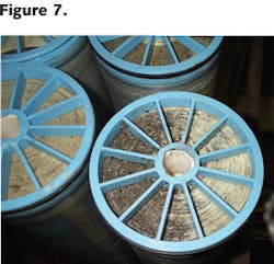
Space limitations prevent a discussion of RO monitoring requirements, but flow, pressure, conductivity, and temperature measurements of the inlet, permeate and reject are very important. These allow the operators to track RO performance and clean the unit before scaling or fouling becomes too severe or even irreversible. Mechanical upsets can damage membranes or membrane support structures, leading to poor permeate quality. Poor microbiological treatment of the RO feed will allow microbes to grow within the membrane spacers and on the membranes, in turn leading to irreversible fouling (see Fig. 7), so careful attention is needed to kill microbes before they reach the RO.
Conversely, removal of oxidizing biocides (e.g., chlorine, bromine or chlorine dioxide) by chemical neutralization just prior to the RO process is critical for operation of most membranes, as the oxidizers will destroy the membrane base material, polyamide.
When properly installed and operated, a reverse osmosis system can remove over 99 percent of dissolved ions in the feed water. A double-pass system, where permeate from the first pass is routed through another set of membranes, will produce an even better product. With some final ion exchange polishing by either mixed-bed units or an electrodeionization (EDI) system, two-pass permeate is suitable for even the highest-purity applications.
References
1. Meltzer, T. High-Purity Water Preparation: For the Semiconductor, Pharmaceutical, and Power Industries. Tall Oaks Publishing, Littleton, Colorado, 2007.
2. Byrne, W. Reverse Osmosis: A Practical Guide for Industrial Users, 2nd Edition. Tall Oaks Publishing, Littleton, Colorado, 2002.
About the Author: Brad Buecker is a process specialist with Kiewit Power Engineers of Lenexa, Ks. He has over 32 years of experience in or affiliated with the power industry -- much of it in steam generation chemistry, water treatment, air quality control, and results-engineering positions with City Water, Light & Power (Springfield, Ill.) and Kansas City Power & Light Company's (La Cygne, Ks.) station. He has written three books for PennWell and many articles on steam generation and air pollution control topics. He has an A.A. in pre-engineering from Springfield College in Illinois and a B.S. in chemistry from Iowa State University.


