Power System Harmonic Fundamental Considerations

by Larry Ray, P.E. and Louis Hapeshis, P.E.
• Tips and tools for reducing harmonic distortion in electronic drive applications for water and wastewater operations.
This paper provides an overview of harmonic considerations for designing industrial and commercial electric power distribution systems. Harmonics can be a particular concern for industrial water treatment facilities, since they typically utilize variable frequency drives (VFDs) for their operations. While conventional power distribution systems accommodate a significant amount of non-sinusoidal current, the design engineer can utilize existing IEEE guidelines and basic software tools to avoid some special circuit and load configurations that exacerbate harmonic distortion problems.
Harmonic Distortion Basics
What’s Flowing on the Wire? – By definition, harmonic (or non-linear) loads are those devices that naturally produce a non-sinusoidal current when energized by a sinusoidal voltage source.
Both current waveforms are produced by turning on some type of load device. The example current in the case on the left in Figure 1 could be produced by an electric motor or resistance heater. The current on the right could be produced by an electronic variable speed drive. The devices could be single- or three-phase, but only one phase current waveform is shown for illustration. The other phases would be similar.
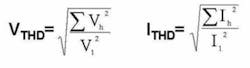
Total Harmonic Distortion – The series of harmonic components that represent a distorted waveform often are described by a single number, total harmonic distortion. In the United States, this is calculated as the sum of all the harmonic components (except the fundamental), divided by the magnitude of the fundamental. This value is represented as THD, or in equation form in Figure 2.
Two Mitigation Techniques
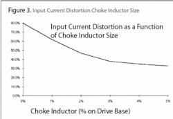
Harmonics Attenuation – Harmonic current distortion is affected by the amount of circuit impedance. In fact, an engineer will discover that placing the same harmonic producing load at two different nodes in a power system will result in two different levels of load current distortion. Power system designers can utilize this effect, called attenuation, as one method of passive harmonic mitigation. The example current waveform in Figure 3 shows the effects of introducing a series line reactor (“choke”) at the terminals of a 100 HP pulse-width-modulated (PWM) adjustable speed drive (ASD). The current total harmonic distortion associated with the ASD drops from about 81% to 38%.
The ASD operation is not adversely affected, provided the line reactor chosen for the application does not exceed approximately 5% impedance relative to the drive base.

Harmonics Cancellation – In addition to attenuation, harmonic current distortion can be reduced by cancellation. Cancellation occurs because individual harmonic components of a distorted current are affected differently when passing through normal power system transformers. The magnitude of harmonic currents, like the 60 Hz component, increases or decreases consistently with the transformer turns ratio.
The phase angle of harmonic components, however, is influenced by the type of connection of the three phase transformer. The 5th and 7th components, for example, experience a 30° phase angle shift through a power system transformer connected delta-wye, as compared with the same current components transmitted through a wye-wye or delta-delta connected transformer.
Computer Techniques
Simple radial networks can sometimes be analyzed utilizing hand calculations. In most cases, though, these calculations quickly become tedious as the circuit size increases beyond a few nodes and devices. Most common computer techniques are based on nodal admittance equations for the network.
Commercially available software tools, like the SKM brand Power*Tools for Windows®, facilitate harmonic analysis of complex systems and loads. These tools provide graphical interface to build a variety of circuit types, including radial, loop systems, and multiple independent systems of different voltage levels. They also contain a large library of conductor, transformer, capacitor, motor and harmonic load types. The library eliminates the need to enter individual harmonic waveforms, for example, by offering the ability to use characteristic models already listed.
VFD Applications
Another software tool, called HarmCalc™ from Schneider Electric, has been developed to facilitate a common harmonic evaluation task: application of variable-frequency drives (VFD) to an existing low-voltage radial power system. While this tool is not accurate for complex systems, or for systems with power factor correction capacitors or harmonic filters, it is widely applicable for evaluating VFD applications. Many consulting engineers and end-users who specify VFD designs accept this tool as a suitable means of estimating VFD effect on a power system. It also is used as a means of evaluating certain mitigating devices like line reactors and drive-isolation transformers, delta-wye transformer connections, and broadband filters.
VFDs and IEEE 519
Institute of Electrical & Electronics Engineers (IEEE®) Standard 519 frequently is quoted in consulting engineer specifications associated with VFD installations. The gist of these specifications is that the VFD vendor assumes responsibility for supplying VFDs that “comply with IEEE 519.” This specification requirement is clearly outside the original intent of the standard, and often unnecessarily increases the cost of a VFD installation.
The original intention of IEEE Standard 519 was to introduce harmonic current and voltage distortion guidelines for electric utilities and their customers. The objective was to establish acceptable levels of current distortion that an individual customer could generate without adversely affecting other electric utility customers sharing the same distribution system. Further, this standard provided recommended limits for electric utility control of voltage distortion that could result from customer harmonic current injection.
Despite the misapplication, this specification requirement has become so widespread that IEEE Standard 519 has effectively become the consensus equipment standard for VFD applications. Given that backdrop, use of HarmCalc and other tools in evaluating VFD installations requires further exploration and definition of terms associated with IEEE Standard 519.
Point-of-Common Coupling
As discussed, the circuit node at which harmonic current and voltage limits were to be evaluated was that point on the electric utility system at which other customers could be served. This so-called point-of-common-coupling (PCC) is described graphically in Figure 4. Often, VFD specifications that require IEEE 519 compliance will also designate the PCC. Generally, the closer this PCC is to the VFD terminals, the more costly the compliance requirements will be.
For PCCs on the electric utility circuit, the utility usually provides this number. The second required value is the estimated or measured demand current of the customer’s total load, IL. The PCC is simply the point in the distribution system at which the harmonic measurements will be measured.
Other Harmonic Issues
Some industrial water facilities face a unique challenge in that they’re connected to their industrial process facility’s electrical distribution system instead of being fed directly by a utility transformer. This means the power they receive from their industrial facility can have a significant harmonic content if the processes of the facility contain non-linear loads. This issue can go both ways, meaning that the industrial water facility itself can create issues for the industrial process due to its non-linear loads. Therefore, if an existing facility is experiencing issues or failures with sensitive electronic equipment, or reduced motor life, a power quality study could be performed to identify possible harmonic issues.

Conclusion
This article introduced some harmonic basics, and tools to identify and mitigate potential harmonic issues. Harmonic issues are well documented, and there is much literature available online and elsewhere to provide a more in depth understanding of the topic, if desired.
About the Authors: Larry Ray, P.E., is the manager of power system engineering for Schneider Electric. Contact: [email protected]. Louis Hapeshis, P.E., is a staff power systems engineer for the Schneider Electric Water Wastewater Competency Center. Contact: [email protected]