Radial Water Well Collectors a Big Draw
by James A. French
• Unique hybrid collector well provides reliable process water supply for challenging industrial site along Mississippi River.
In the 1990s, a global company known for adopting cutting-edge technology situated a new paper products plant along the west bank of the Mississippi River near Cape Girardeau, MO, south of St. Louis. The river, which was to be the source for the plant’s process water, had a normal turbidity level unsuitable for the plant’s requirements without additional treatment. A typical treatment strategy would have involved building a clarifier plus the ongoing expenses associated with operation and maintenance of the treatment system. The plant owner was able to avoid pretreatment problems with a 3,000-gpm horizontal collector well that utilizes the sand and gravel riverbed for pretreatment.
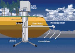
A typical collector well consists of multiple lateral well screens projecting from the bottom of a caisson installed to various depths below the water table. In this case, a 70-ft. deep, 13-ft. diameter caisson was designed with six laterals and adequately supplied the operations. More recently, a second well was required for a plant expansion and was engineered to deliver 4,500 gpm of pre-treated water. The well features a unique design that ensures a reliable year-round supply under low flows in the river channel.
Pioneered by Leo Ranney in the 1920s, horizontal collector wells have evolved into a mature alternative to traditional surface water intakes where a large supply of water is needed for industrial processes, power generation, cooling towers or raw water supply for municipal utilities. In this instance, the collector well is located in an aquifer fed by a nearby river. The raw water drawn from the aquifer by the collector well is subjected to riverbank filtration (RBF) as it travels through the sand and gravel bed, removing turbidity and most other contaminants
Well #1 consists of a reinforced-concrete caisson extended to a 70-ft. depth in the alluvium, sediment deposited by water flow such as riverbeds. A series of six gravel-packed horizontal laterals – 175-ft. in length – extends from within the caisson in a radial pattern at different elevations into the aquifer. The laterals are fitted with stainless steel wedge-wire screen with slot sizes calculated to deliver the desired entrance velocity. As powerful pumps draw from the well, the drawdown creates a cone of depression around the laterals that steadily spreads out to set up induced infiltration from the river’s surface source whose water percolates downward through the sediment and strata to reach the laterals and recharge the well. The site for Well #1 offered suitable unconsolidated alluvium to purge the water supply of turbidity at a reliable flow. The well produced water that was low in turbidity (1 to 2 NTU), and was less subject to temperature fluctuations and surface waterborne organisms.
Performance of the original well made a second, larger-rated horizontal collector well the preferred source to support a more recent plant expansion. The same design-build team was assembled again for the Well #2 project, with Ranney Collector Wells (formerly Collector Wells International) serving as the well designer and contractor and proceeded in lockstep with the schedule for the rest of the plant expansion.
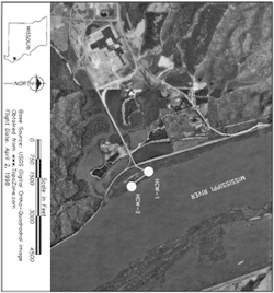
The only possible location for Well #2 along the plant owner’s limited river frontages was approximately 1,000 feet downriver and presented a different set of conditions. These included a bedrock depth that ruled out a deeper well and seasonal changes in the river flow that often caused the shoreline to recede by 200 feet. These factors indicated a 2-mgd shortfall could be experienced in the volume required for the plant’s year-round operations. The solution translated into a second horizontal collector well with a unique combination of laterals and a supplemental river intake. The screened intake line allows the unit to more than double the well’s capacity under the same low-river conditions that reduce the saturated thickness of the aquifer that feeds the laterals off the caisson.
Ranney Collector Wells, part of Layne Christensen Co., designed Well #2 to be 80 feet deep with three 12-inch diameter laterals extending 200 feet out, feeding into a manifold line system within the 16-ft. diameter caisson. Grade elevation at the site is 350.9 msl (mean sea level) – with the laterals placed at elevation 294.16 msl – i.e., if you subtract 294.16 from 350.9, you get 56 feet for the first placement of the laterals. The manifold system at the bottom of the collector directs the water collected by the lateral outlets into a single discharge pipe. Control valves in the line manifold can selectively isolate an individual lateral for maintenance while the others continue to draw water.
The yield off the collector wells, however, depends on the river stage. At this location along the Mississippi River, this can fluctuate by as much as 30 feet per year. A supplemental intake line, unique to this project, compensates for these fluctuations. The river intake consists of a single 30-inch diameter line extending 244 feet out into the channel. The design-build crew micro-tunneled the line 200 feet outward from the caisson at elevation 308 feet. At the line’s terminus in the channel, it’s fitted with a pile-supported, 30-inch copper nickel wedge wire “T” fixed screen equipped with an air purge backwash system. The design exceeds EPA Rule 316B relative to protection of aquatic life at water intakes. The water drawn directly from the river channel flows into a single line in the manifold array and is isolated from groundwater drawn by the laterals. The two water sources for the plant are then blended farther down-line.
During low river flow periods, the river intake compensates for the reduced yield off the collector wells and coincides with the lowest turbidity levels in the channel. Mixing of these two sources also counteracts an inherently high iron content of the well water. The dual-source design not only achieves sufficient supply for the plant, but the drawdown effect enhances ongoing percolation into the aquifer.
The water volume through the hybrid well will be the river level minus head loss. By monitoring the well’s yield, it has been demonstrated the supplemental river intake allows Well #2 to maintain intended production levels even during low river flows. It also shows this design continues to offer a favorable return on investment by eliminating otherwise significant costs of pretreatment.
About the Author: James A. French is vice president of Ranney Collector Wells, of Columbus, OH. It’s a division of Reynolds Inc., which Layne Christensen Co. acquired in 2005. Collector Wells International Inc. was combined with the Columbus company when it was acquired in 2006. Contact: 877-472-6639, [email protected] or www.collectorwells.com


