Computer Simulation Saves in Design of Hydrodynamic Vortex Separator
Hydro International plc, a British company with U.S. headquarters in Portland, Maine, recently decided to develop an economical but effective system for removal of sediment and other pollutants from stormwater in smaller industrial, commercial and residential facilities. Engineers quickly determined the company’s existing products designed for larger facilities couldn’t be scaled down to the required size, making it necessary to start the design process from scratch. In the past, this would have required at least three iterations of building and testing prototypes at a cost of about $20,000 each. Instead, the company’s engineers used computational fluid dynamics (CFD) software to develop an optimized design in less time and at considerably lower cost.
Stormwater discharges make a significant contribution to pollution problems in most urban areas. This is because pollutants such as litter, oil, grit, pesticides, metals, fertilizers, etc., tend to settle on impervious surfaces such as streets, parking areas, driveways and sidewalks. A heavy rainstorm can wash these untreated pollutants into drainage systems. Typically, these inlets eventually discharge into nearby streams. Recent environmental studies have shown stormwater runoff plays a significant role in the problems of 13% of polluted rivers, 21% of polluted lakes and 45% of polluted estuaries.
NPDES Phase II Rules
Many industrial and commercial facilities are facing the prospect of needing to address the impacts of stormwater runoff as part of the Environmental Protection Agency’s (EPA) National Pollution Discharge Elimination System (NPDES), Phase II Stormwater Program. Phase II is the second component of a two-part program-see: http://cfpub.epa.gov/npdes/stormwater/swphases.cfm-to improve the quality of the nation’s streams, rivers, lakes and estuaries by managing stormwater runoff from urban and suburban areas, construction projects and industrial sites. Phase I, issued by the EPA in 1990, covered medium and large municipalities, construction sites over five acres in size, and 10 categories of industrial activity. The Phase II program is the next step and covers smaller municipalities, urban areas adjacent to municipalities, and construction sites over one acre.
In developing a product to address challenges of facilities covered by Phase II requirements, Hydro’s goal was to remove 90% of sediment and avoid washout of stored pollutants while also capturing oil and floatables. The idea was to let the fluid motion through the device do all the work so it could operate without any moving parts and without filtration systems that could potentially clog and require maintenance. Engineers recognized at the outset of the design process the challenges involved in meeting these goals through hydrodynamics alone. The traditional approach to designing this type of separation device is to build a prototype, test it to find out how it works, make assumptions on how its performance could be improved, and then build another prototype to start the process anew.
Design Problems
There are several problems with the traditional approach. First, the geometry of hydrodynamic separators is typically quite complex, so the cost of building and testing a prototype can exceed $20,000 and take more than eight weeks. Second, though physical testing of prototypes can easily determine device performance, it provides little insight into why the device performs as it does. This is because it’s difficult to visualize fluid dynamics, even when the prototype is made of a clear material. The only way to obtain even limited visualization is through high-speed video imaging, which adds substantially to the cost of testing. The result is that engineers are frequently left guessing as to why a prototype failed to perform as hoped; instead, they must rely on intuition or guesswork to design the next version.
This new process has overcome these difficulties by using computational fluid dynamics (CFD) to simulate the performance of hydrodynamic separators and other flow-intensive devices. One major advantage of CFD is that a model can be created and evaluated within a week and at less than 20% of the cost of physical prototyping. Another advantage is CFD provides far more information about reasons behind the performance of a design concept. For example, it can provide flow velocity and direction throughout the analytical domain and can also trace the path of particles of different sizes as they flow through the system. Of course, critical in any simulation is how closely it’s able to duplicate reality.
Simulating reality
Hydro International engineers evaluated several different leading CFD software packages and selected Fluent software from Fluent Inc., of Lebanon, N.H., because it demonstrated the ability to closely and consistently correlate with physical test results. Another advantage is it makes it easy to determine efficiency of a separator by simulating injection of large numbers of particles into a model and keeping track of how many end up in which location. The software also makes it easy to graphically define geometry and boundary conditions of the model and offers a wide range of analysis options that make it possible to solve nearly any problem.
Hydro engineers modeled several design concepts prior to the prototyping stage to finalize the design as much as possible before beginning that phase. The engineers wanted a design that provided the following flow characteristics: 1) a structured rotary flow around the vertical axis of the chamber to produce the rotary forces that contribute to separation; 2) high and uniform downward velocity through the middle of the chamber and little or no vertical velocity around the outer walls, where rotation should dominate; and 3) in simulating particle flow through the device, capture of at least 90% of the particles entering the device-without washout.
Evaluating performance
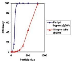
Hydro engineers began by modeling a simple cylindrical design that featured a large central tube for outlet control and a bypass within the treatment chamber. The CFD results showed this design didn’t come close to meeting the company’s performance requirements. Its fluid dynamics lacked structured rotational flow and the vertical flow velocity in the central region was lower and less consistent than desired. So it wasn’t surprising that the separation efficiency of this design wasn’t particularly high. It only removed the medium to coarse sized particles, allowing over 90% of the finer particles to escape. While this design was disappointing, it contributed to the design process by providing insights on the geometrical requirements for good separation efficiency. Engineers modeled several other designs that showed relatively weak performance but provided additional design insights.
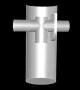
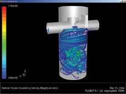
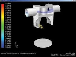
Next, engineers modeled a more complicated peripheral bypass design that features two opposing tangential inlet/outlet chutes and provides bypass around the chamber periphery. This design was conceived based on insights from earlier designs, with the goal of achieving structured rotational flow by introducing the stormwater tangentially through the inlet chute. The outlet chute is positioned to discharge treated stormwater in a direction opposite that of the circulating flow, allowing solids to be swept past the outlet. An integral bypass eliminates the need for an additional structure. Higher flows bypass the treatment chamber where a stable flow regime is maintained, preventing the washout of stored pollutants. A draw-off port diverts floatables to the treatment chamber prior to bypass.
Meeting All Objectives
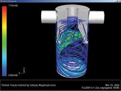
The simulation of the peripheral bypass design showed it met all of the original design objectives. A structured rotational flow was clearly visible around the outer section of the chamber. A high and consistent downward velocity was seen in horizontal cross-sections of the chamber. Most importantly, CFD predicted the design would capture over 90% of the target sediment at the design flow rate of 20 liters per second (lps). The simulation also showed that at 30 lps, over 90% of the target sediment would be retained in the sediment storage area.
Conclusion
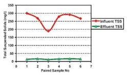
Physical testing by Hydro International and witnessed by the Maine Department of Environmental Protection (DEP) verified the CFD predictions. In the Maine DEP tests using OK110 sand, the device performed at an average efficiency above 90% for fine particle removal over a series of six tests. This was well above the 80% level required to achieve certification. Hydro released the product, called First Defense®, based on this design, targeting factories, parking lots, vehicle maintenance yards, strip malls, convenience stores, truck stops, condominiums and apartments, and other facilities affected by the new Phase II regulations. The product has been successful, exceeding budgeted sales projections to date. Hydro management believes its success is partially due to use of CFD to quickly and inexpensively iterate to an optimized design offering the performance needed by the intended market at an economical price. And Hydro saved $50,000 in the design phase.
About the Author:
Bob Andoh is group technical director of Hydro International, whose U.S. operations are based in Portland, ME. He can be reached at 207-756-6200 or www.hydro-international.biz. For additional information, contact Fluent Inc. at 603-643-2600 or www.fluent.com.

