Membrane Technologies in Industrial Water Treatment
In a Zenon Environmental presentation a few years ago, the words on a slide captured my attention as being both accurate in the moment and a predictor of the future. The words were: “Membranes are to water treatment what the microchip is to information technology.” The boom in membrane water treatment the past few years, with relatively high growth rates in existing market segments and expansion into new market segments, I think, validates that prediction.
There are two general categories of membrane water treatment technologies. These are:
1. Pressure-driven technologies
2. Electrical potential-driven technologies
In this article, pressure-driven membrane water treatment technologies will be discussed. In the second article of this two-article series, electrical potential-driven membrane water treatment technologies will be covered.
Pressure-driven membrane water treatment technologies include the following:
• Microfiltration (MF)
• Ultrafiltration (UF)
• Nanofiltration (NF)
• Reverse Osmosis (RO)
• Membrane Degasification (MD)
Pressure-Driven Membranes
Pressure-driven membranes are designed to either allow water molecules to pass through but restrict the passage of dissolved and suspended contaminants, or are designed to restrict the passage of water molecules and only allow dissolved gases to pass through. Membranes that allow water molecules to pass through are relatively hydrophilic (water attracting). Membranes that restrict the passage of water molecules are relatively hydrophobic (water repelling).
Hydrophilic membranes are used in MF, UF, NF and RO water treatment technologies. Hydrophobic membranes are used in membrane degasification water treatment technologies.
Dissolved and Suspended Contaminants
Dissolved contaminants, like ions and small organic and silica molecules, change the boiling point, freezing point, viscosity and osmotic pressure of an aqueous solution. They will never settle to the bottom of a sample. Dissolved contaminants are extremely small, with a rough size of less than 0.01 micron (μm).
Suspended contaminants are bigger than dissolved contaminants. Those greater than 30-50 μm are visible to the naked eye. Colloidal contaminants are actually suspended - but as with dissolved contaminants, they’ll never settle to the bottom of a sample.
Particle-Size Scale
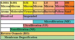
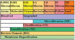
Figure 1 depicts a particle-size scale from 0.0001 μm to 1,000 μm. Dissolved water contaminants are roughly in the size range of 0.0001-0.01 μm. Suspended contaminants are roughly greater than 0.01 μm. From Figure 1 you can see examples of particles in various size ranges. As seen in Figure 1, bacteria are identified as being from 0.1 μm to 10 μm. While most are greater than 1 μm in diameter, recent research has identified very tiny dormant forms.
Figure 1 also identifies roughly the size range of contaminants that each membrane technology will reject. For example, RO membranes will reject essentially all dissolved and suspended contaminants. RO membranes are only used, however, to remove dissolved contaminants.
MF and UF Technologies
The pore size of MF water treatment membranes is typically 0.1 or 0.2 μm. The pore size of UF water treatment membranes is typically 0.01-0.04 μm. As can be seen in Figure 1, MF membranes remove most particles greater than 0.1-0.2 μm in diameter. UF membranes remove essentially all suspended particles.
MF and UF membranes reject suspended particles based on the size of the particles. If a solid particle is greater in diameter than the diameter of the pores in the membrane, it can’t pass though. Certain semi-solid particles a little bigger than the pore size, however, may be able to “squeeze” through the pores.
NF and RO Technologies
Membranes that remove dissolved contaminants are reverse osmosis (RO) membranes. Dissolved contaminants create an osmotic pressure (the pressure of osmosis) that must be overcome in order for water molecules to pass through the membrane from the higher dissolved-contaminant-concentration side of the membrane (the feed water) to the lower dissolved-contaminant-concentration side of the membrane (the permeate).
In the United States, we commonly call the highest rejecting water treatment membranes “RO membranes.” NF membranes are “looser” RO membranes that reject dissolved contaminants greater than around one nanometer (0.001 μm). They may reject over 99% of dissolved contaminants and reject close to 100% of suspended contaminants.
NF and RO membranes reject suspended particles due to size exclusion. Dissolved contaminants that possess a charge, like sodium (Na+), chloride(Cl-), calcium (Ca+2) and sulfate (SO4-2), are rejected based on their charge; in general, the greater the charge, the greater the rejection.
Uncharged dissolved contaminants are rejected based upon their size. For dissolved substances, size is typically inferred from molecular weight. NF membranes reject most uncharged contaminants with a molecular weight greater than roughly 200-400. RO membranes reject most uncharged contaminants with a molecular weight greater than roughly 100-200.
Membrane Degasification
In the case of water degasification membranes, the design is for dissolved gas molecules to leave the water. A hydrophobic membrane is used so that water molecules will not pass through but dissolved gas molecules can.
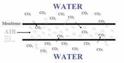
The amount of gas dissolved in water is proportional to the amount of that gas in the atmosphere in contact with the water. The Earth’s atmosphere contains around 78% Nitrogen (N2), 21% oxygen (O2) and 1% all other gases. If air is on one side of the membrane, and on the other side of the membrane there is well water with no oxygen present but lots of carbon dioxide (CO2) present, there will be a net movement of CO2 out of the water and a net movement of O2 into the water (atmospheric N2 will also equilibrate with N2 in the water, but N2 is typically not a concern for most water treatment applications). Figure 2 illustrates this.
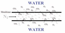
In applications where low levels of oxygen are also desirable, N2 is used as the purge gas resulting in a net movement of both CO2 and O2 out of the water (and a net movement of N2 into the water). Figure 3 illustrates this.
Applications
MF and UF membranes are used for suspended solids removal or concentration. UF membranes are also used for the removal of certain organic compounds. Applications include final filtration in the semiconductor/microelectronics industry, concentration of juices, pretreatment of feed water going to NF or RO membrane units, cheese whey fractionation/dewatering, removal of suspended solids for wastewater treatment and many other applications.
NF membranes are commonly used to produce drinking water from well water sources that aren’t too high in salinity. RO membranes are used in many applications where the level of dissolved contaminants must be reduced by a very high percentage. These membrane systems are common in drinking water applications from both brackish and seawater sources. They’re also common in a host of industrial applications including production of high purity water for semiconductor/microelectronics and pharmaceutical/biotech products, food and dairy products, beverage products, high-pressure boiler feed water, “spot-free” car wash rinse water, commercial dishwashing water and more.
Membrane degasification is commonly used for the production of high purity water in the semiconductor/microelectronics industries. The power generation industry is another application where the removal of CO2 and O2 is critical.
Conclusion
Membrane water treatment is growing at a fast pace. If “membranes are to water treatment what the microchip is to information technology,” then “water treatment specialists are to water treatment what IT specialists are to information technology.” Water treatment professionals need to learn as much as possible about these membrane technologies. There’s a world of opportunity for knowledgeable, capable water treatment professionals.
About the Author: David Paul is president of David H. Paul Inc, an advanced water treatment training and multimedia production firm. He has over 27 years of membrane water treatment experience as an operator, manager, instructor and consultant. Contact: [email protected] or www.dhptraining.com.


