Guide to Measuring pH in Challenging Processes
By Jim Smith
Plant operators responsible for ensuring product quality, resource efficiency, profitability and environmental compliance require pH analysis instrumentation that lasts longer, especially in harsh, dirty or elevated temperature applications that typically tend to reduce life. Today's pH sensors incorporate new technologies that lengthen sensor life and reduce the required maintenance hours for cleaning, calibration and replacement.
Monitoring Challenges
Experience has shown that some pH sensors last years while others only last weeks. Some sensors need routine maintenance (i.e. cleaning) every month while others must be cleaned daily. This is because each process is a unique environment and pH sensors are not one size fits all. Sensor life and performance are dependent upon the environment in which the sensor is used. For example, a pH sensor in a high-coating wastewater environment may require cleaning much more often than the same model sensor in a metal finishing plating rinse water application. This rinse water application, however, may contain heavy metal ions that reduce the lifetime of the sensor considerably. Plant operators can optimize performance by selecting the sensor best suited for each specific application.
Sensor Coating
Coating of the reference junction remains the primary challenge to pH measurement in dirty applications. A coated sensor cannot adequately sense the process and will respond very slowly, if at all. Dirty applications impact the bottom line by requiring more handling by personnel or by reducing the availability (and benefit) of the pH measurement.
As sensor technology has evolved, the industry has seen the emergence of coating-resistant sensors. One new technology incorporates a reference junction with a large surface area that extends the time between required cleanings by providing many more paths for the reference junction to contact the process solution. In addition, this reference junction design has extremely small pores that are too small for most particulates and suspensions to penetrate. While regular cleaning will still be necessary to assure accurate pH measurement, this kind of advanced reference technology extends the time between required cleaning, thus reducing maintenance costs.
Cleaning pH sensors can be done either manually or on-line. For on-line cleaning, several cleaning methods are available. One method uses a jet spray cleaner that directs a spray of water or cleaning solution at the measuring tip of the pH sensor. Another method incorporates a sensor retraction device that removes the sensor from the process and features a sensor tip cleaning chamber. These cleaning methods may be automated when used with instruments that support this feature. These instruments may include interval timers that take the loop off-line when a timed interval (hourly, daily, weekly, etc.) is reached. Or, if the analyzer and sensor incorporate predictive sensor diagnostics, the analyzer performs self-checks and detects certain problems in the electrode, then depending on the problem identified, can trigger various alarms and actions, such as turning on the jet spray cleaner.
When manual cleaning is performed, the sensor is removed from the process. It is most cost-effective to select sensors that are quick and easy to remove from and re-install into the process. For example, through-the-valve retractable sensors allow sensor cleaning and calibration without the need to shut down the process. Another method employs a quick-lock assembly that allows the sensor to be removed without unscrewing it from a threaded fitting. One offering incorporates a quick cable-to-sensor release connector that eliminates cable twisting.
Reference Contamination
Reference contamination is another challenge associated with pH measurement. The reference is typically a silver-silver chloride-based electrode that can be damaged when poisoning ions such as lead, iron, chrome, cyanide and sulfide enter the reference and react either with the silver wire or with the chloride solution. When these ions enter the fill solution in the reference junction, they form insoluble precipitates with the silver ions in the fill solution. There's no initial effect on the potential of the reference because the silver ions lost to precipitation are replenished by silver ions dissolving off the silver chloride coating of the silver wire. It's not until the silver chloride coating is completely lost that a large change in the potential of the reference occurs. At this point, however, the reference electrode must be replaced.
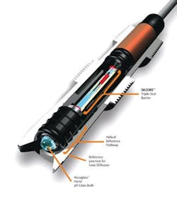
New technologies help inhibit reference contamination to prevent the compromise of the pH measurement and significantly increase sensor life. These technologies slow the onset of reference contamination by barring entry into the sensor or lengthening the path to the measurement electrode. One method uses multiple barriers to inhibit migration of the poisoning ions to the silver reference. Some sensors are designed with long, helical reference pathways that force ions to travel a long, winding path to the silver-silver chloride reference. The objective of the helical pathway is to require a long diffusion path without requiring a large unwieldy sensor. This concept works well in conjunction with a viscous gel internal fill solution that also slows down the ion-diffusion rate. Another long-life sensor technology is a triple-seal contaminant barrier that can prevent moisture and material impurities from migrating to the electrode's metal lead wire.
Cracked Glass
Another hazard of pH measurement is physical damage to the glass due to impact or temperature cycling. This concern has led some manufacturers to offer sensors made with new glass formulations that are designed to resist cracking and to use materials with similar temperature expansion coefficients. Nonetheless, it is still good practice to prevent temperature shock by allowing sensors to cool slowly and to locate pH sensors away from direct impact by damaging particles. These improved glass technologies not only increase sensor life, but also improve sensor performance for more accurate pH measurements.
Damaging Energy
Sensors can fail if vibrations or shocks through the process line damage the glass electrode. To prevent vibrations in the process from damaging the sensor, pH sensors may incorporate technology to transfer damaging energy away from the rigid glass-to-metal seal within the glass electrode body.
Accurate Calibration
The best way to verify the accuracy of a pH analyzer and sensor is by two-point buffer calibration. A buffer is a standard solution formulated to resist changes in pH caused by external contaminants. Two different buffer solutions, which are usually at least three pH units apart, are used in pH sensor calibration. This allows the pH analyzer to calculate a new slope (pH glass efficiency) and zero offset (reference offset) for use in calculating the pH from the millivolt potential and temperature measurements. The magnitude of the slope indicates the condition of the glass electrode, while the zero offset generally indicates the degree of reference poisoning. An ideal pH sensor would have a slope of 59 mV per pH unit and a very low zero offset. In practice, a slope of 57 or 58 and a zero offset of less than ±10 mV can be expected.
There are a couple of common buffer calibration errors to avoid. Both are related to temperature. Buffer solutions have a stated pH value at a specific temperature. The actual pH of many buffers will change with the temperature. The pH of the buffer solution at various temperatures is usually listed on the bottle and the value at the appropriate temperature must be used to avoid errors in the calibration. For convenience, newer analyzers incorporate a buffer recognition feature that automatically corrects the buffer value for differences in temperature.
Another common buffer calibration error is simply operator haste. If a buffer calibration is done too quickly without allowing the pH sensor to fully respond to the buffer solution, calibration errors will result. For example, if a pH sensor has been in a warm or elevated-heat process and is not given enough time to cool down to the temperature of the buffer solution, the calibration will not be accurate. To prevent this error, some pH analyzers feature buffer stabilization capabilities that prevent the analyzer from accepting a buffer pH reading that has not reached a prescribed level of stabilization.
Continuous Sensor Diagnostics
Sensor failures can occur slowly, such as the gradual loss of pH electrode slope or poisoning of the reference electrode. Or failures can be sudden, as in the case of pH electrode breakage, or coating and plugging of a reference electrode. In any event, failure or impending failure, may go undetected until the next routine buffer calibration. Built-in diagnostics for pH sensors can detect these problems in real-time and alert plant operators to potential problems. This allows plants to plan more effective maintenance schedules and get the longest life possible from the sensor.
These self-tests are enabled by additional design features that turn the pH sensor into a multiparameter diagnostic device. For instance, a typical pH analyzer may continuously measure pH, temperature, glass impedance (to monitor breakage), and reference impedance (to monitor coating). Furthermore, communication using digital communication protocols allows transmission of all of these parameters to a remote location for viewing. These diagnostics serve as inexpensive insurance against the possibility of unknown failures leading to out-of-control processes and environmental problems.
Diagnostic parameters can serve as simple alarms to indicate failure, or as diagnostic tools for scheduling maintenance. The full benefit of sensor diagnostics is realized in conjunction with integrated asset management software packages. These packages allow users to easily manage their plant operations, saving time and money by setting up and configuring analyzers, reading process variables and troubleshooting problems from a personal computer or a host anywhere in the plant.
Plants must conduct a cost/benefit analysis to confirm that the benefits in man-hour savings and reduced unscheduled maintenance shutdowns justify the added cost of predictive diagnostic technologies. IWW
About the Author: With over 21 years of experience in industrial processing, Jim Smith is manager of pH measurement products from Emerson Process Management, Rosemount Analytical. Additional company and product information can be found at www.raihome.com and Smith may be reached at [email protected].


