Saving water and tailings dam space: Part 1 — mining’s challenge and a pilot centrifuge solution
By Eric Gentis, Stephen Benyo, Guillermo Flores, Gabriel Rodrigues and Dustin Miller of Flottweg Separation Technology
This article is the first in a two-part series exploring how medium-sized mining operations can address the growing challenges of water scarcity and limited tailings dam capacity. Drawing on a recent pilot project at a fluorspar mine in central Mexico, Part 1 sets the stage by examining the industry’s water management issues, the limitations of traditional solutions and the potential of mining-grade decanter centrifuge technology. It also details the case study background, pilot unit setup and feedstock characteristics — laying the groundwork for the operational results and lessons learned to be presented in Part 2.
Small-to-medium-sized mines and quarries have water problems that include a shortage of pond/dam space, a shortage of water caused by climate, regulations, cost and other reasons. Specification limits on water intended to be returned to ground water, or even too much water contaminated by sediments and ultra-fines can also affect the water supply.
The traditional solution is using tailings dams or adding a chamber filter (plate-and-frame) press to dewater the tailings. This solution requires significant capital investment and infrastructure and comes with a large footprint requiring significant real estate to be quarantined below the tailings dam site. The use of dams does not recover much of the process water, relying on evaporation and settling to slowly reduce the liquid load in the dam. Finally, dams and ponds are not portable, and associated civils/structure costs add to Capex.
A reliable, cost-effective alternative is explored in-depth by reviewing a trial of a pilot plant using a decanter centrifuge that is specifically designed to withstand the rigors of a mining application.
The pilot plant test showed impressively dry solids with zero polymer use, and low suspended solids in the centrate liquid (with some staining from a non-toxic organic tannin).
Background and challenges
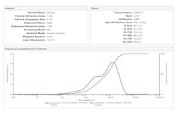
The mining customer in this case study already owns several Flottweg Z92 (920mm bowl diameter) decanter centrifuges operating successfully (24/7) at their main processing plant, dewatering their tailings and recovering most of their (very) expensive process water.
The customer wanted to run a smaller pilot unit at a different, more remote location where they operate another process plant. The goal was to check whether the conditions there are also suitable to invest in another battery of Z92s for this second operation. They are rapidly depleting their current tailings dam space at this site and have a very significant water cost due to their location in central Mexico’s arid region.
Flottweg provided a suitably wear-protected Z5E mining decanter centrifuge (530mm bowl diameter) to run as a pilot for a month. This size unit can effectively mimic the large unit operations and is regularly used for this kind of scale-up predictability pilot in mining applications.
Operation of the pilot centrifuge was 24/7 during the pilot period. Regular sampling of the input feed material, the output solids and output liquid (centrate) was performed by trained and qualified operations staff on a regular basis throughout the pilot period. These samples were analyzed for their solids and moisture contents on site in the Flottweg portable laboratory, immediately after capture.
After installation and start-up, 117 separate tests were taken throughout 12 days. These 117 samples form the basis for the graphic interpretation appearing later in this report.
The process
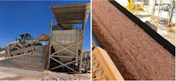
Due to process plant and tailings dam space constraints at the original mine/plant site, pre-crushed material is trucked by road more than 130 km into this location. Typical road haul trucks are double haul of the land-train variety (usually 2 x 22 metric ton trailers making up the so-called “fulles” in Mexico).
This mineral material is approximately 58% fluorspar (CaF2 - Specific Gravity of 3.1; Mohs hardness #4), with the balance being silica from sandstone/mudstone/siltstone (SG of 2.67; Mohs #7) and calcium carbonate (SG of 2.7; Mohs #3). Abrasiveness for the mixture is around Mohs hardness #6 due to the significant load of silica present — and for the total minerals feed mix the SG is quite high at around 2.8.
Potable water is trucked in by a fleet of water bowsers, as the site is practically waterless.
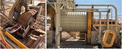
Dry mineral feedstock is mixed with water at approximately a 2.5:1 ratio (water to dry feedstock) and this slurry is then sent to a series of two ball mills in sequence for further reduction. Oversize minerals and contaminants (mainly detonation cord plastic residue from mine blasting operations) are mostly trapped by a rotating trommel-style sieves (mesh +10mm and +5mm) on each mill.
The resultant finer slurry produced by the ball mills is sent to a series of hydro-cyclones where the overflow is forwarded to the conditioning tanks. At the same time, the underflow carrying oversized minerals is returned to the sequential ball mills for further reduction.
In the conditioning tanks, carboxylic acid is added to help flotation of the fluorite. To neutralize the acid, soda ash is added to bring the slurry pH back to the 7.7 pH range. Starch is also added to help separate out the silica.
Finally, the tannin Quebracho (from the South American “axe-breaker” hardwood tree) is added to help separate the carbonates and allow ease of flotation recovery of the fluorite. This mineral mix is then allowed to condition for approximately one hour before being pumped to the 3-tier flotation process.
In the flotation process, the mixture is aggressively agitated both mechanically as well as by aeration to create suitable froth production, and the valuable fluorite is recovered in the traditional froth sweeping process.
This fluorite-bearing liquid is run over a vacuum belt filter to dewater, and the recovered fluorite at 97% pure is then bagged for sale. The recovered depleted liquid is sent to the centralized wastewater collection point.
All other waste from the flotation process (included silica and carbonates) is also directed to the smallish collector tank on the western side of the plant, from which it usually pumped to the tailings dam.
For the period of the pilot trial, the product from this collector tank is the feed material for the decanter centrifuge. Some tramp stones (mostly sized +3-10mm) in this main collector tank still found their way into the feed pump and the centrifuge.
Normally, a mesh screen would be installed to remove anything over 3mm, but as it was not possible to stop the process plant to weld in this screen in place during the trial period, these stones were accepted as a hazard.
Undesirable feed size or not, the test results did not show any significant negative impact from these tramp stones, nor was any vibration detected in the centrifuge as it processed this oversize feed.
Solids in this feed slurry typically range around 11%-16%, but during the trials it was apparent that this could regularly be on the lower limit — partly due to the recirculation of the centrifuge’s centrate output back to the waste collector tank.
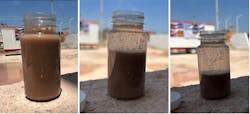
Visually, the silica in this feedstock resembles beach sand. The Quebracho tannin is very fine and creates a reddish hue to all liquids, but it was observed to settle over time.
To illustrate the settlement of the minerals in the liquid: The below left image shows feedstock samples immediately after collection at point of sample; then the center image is the same sample after 10 minutes; then finally the right image after total time of 30 minutes. The staining on the inside sides of the bottle on the last two images is from the Quebracho tannin and is typically ultrafine (well below 1µm).
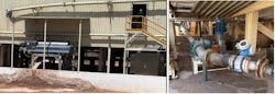
The Z5E centrifuge was mounted on the eastern side of and below the main flocculation plant, due to the need to drop the solids by gravity into an existing concrete holding bunker from which it was periodically removed by a front-end loader.
The feed point from the wastewater exit of the plant is, as mentioned earlier, located on the western side of the plant. This could not practically be changed for the trial. Consequently, the feed line needed to be much longer than the usual 3-5 meters. The total distance from the waste exit point (the feed line for the self-priming lobe pump) was 40-plus meters long with very little elevation drop (less than 1 meter).
The coarser silica content of the feed rapidly settled in the bottom of this longer- than-usual feed pipe, restricting the feed flow to the centrifuge. A work-around was created where the feed line was regularly flushed, but this rapid flow-reduction meant that the flow was generally less than optimal.
Notwithstanding the above, the test results showed negligible difference in solids dryness or centrate clarity — whether at full flow or restricted flow.
For the duration of the pilot trial, it was arranged that the solids are deposited by gravity on an angled steel slide under the centrifuge, from where they end up in a concrete bunker. The mine diverts its feed front-end loader to collect the solids accumulating periodically, and this is then moved to their tailings dam. In steady state, this will be gravity fed onto a double screw conveyor and then fed onto conveyor belt series to send directly to the tailings dam.
Also, for the duration of the pilot trial, the resultant clear centrate from the centrifuge is fed by gravity back into the wastewater collection pond. The slight reduction in percentage of overall solids in the feed (from typically the 14%-16% range; down to the 11.5% -15% range) can be largely ascribed to this recirculation.
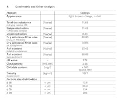
Feed condition and composition
Waste process water and depleted flotation feed that has been collected in the tailings tank is then agitated and fed to the decanter centrifuge through its 75mm (3-inch) feed port.
As laboratory analysis of this feed material shows, the suspended solids range from as low as 11% to as high at 23% w/w. Practically, the customer advised that they found that it is mostly in the 14% to 16% range.
Feed pressure is maintained between 1 and 2 bar (15 to 30 psi) by a positive displacement, self-priming lobe pump.
Particle size distribution of the solids in the feed to the centrifuge show a range from Dv10 at just under 11µm; Dv50 at around 70µm; and Dv90 at over 200µm.
Solving problems with a successful pilot process
The pilot trial at the central Mexico site brought together a challenging operational environment, a demanding feed material and a mining-grade decanter centrifuge built to handle both. With the unit installed, feed characteristics documented and early operating adjustments in place, the stage was set for a month of continuous operation and detailed data collection.
In Part 2, we will examine the results — how the centrifuge performed under varying conditions, what the data revealed about optimizing separation efficiency and the practical lessons that point toward full-scale implementation.