Makeup water pretreatment reliability: Keeping ultrafilters clean
Key Highlights
- UF pretreatment effectively removes suspended solids, protecting RO membranes from particulate fouling and enhancing overall system performance.
- Regular clean-in-place (CIP) procedures, including chemical cleaning and air scour backwashes, are essential to prevent irreversible membrane fouling and maintain efficiency.
- Monitoring parameters such as transmembrane pressure (TMP), permeability, and differential pressure help operators identify when cleaning is needed before performance declines.
- Choosing appropriate cleaning chemistries based on foulant types is crucial; oxidizing biocides are compatible with UF membranes, but residual oxidizers must be removed before RO units.
- Integrity testing, like pressure decay tests, ensures membrane fibers are intact, preventing performance issues caused by leaks or physical damage.
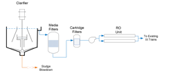
Figure 1. Clarification/filtration was very common for ion exchange system suspended solids pretreatment. As RO technology matured, units were retrofitted into makeup water systems.
Reverse osmosis (RO) has become an integral process for high-purity makeup water production at power generation facilities, chemical plants, pharmaceutical facilities and other industrial operations. However, the tight spacing of spiral-wound RO membranes requires protection from the suspended solids normally present in raw water supplies. Another membrane technology, ultrafiltration (UF), has become the pretreatment method of choice in many applications to remove suspended solids upstream of RO systems. UF operation is often so stable that it is easy to forget that these membranes need periodic cleaning to prevent irreversible fouling. This article examines monitoring techniques for UF cleaning requirements and how to select proper chemistry to address what can be a variety of foulants.
The evolution of membrane technologies
High-purity makeup water treatment technology evolved with the growth of the power industry in the last century. The development of synthetic ion exchange (IX) resins represented a great step forward. But even when relatively pristine waters served as the feed source, demineralizer run times were often limited to less than a day before resins reached exhaustion, which then required regeneration. With the maturation of RO technology during the final decades of the last century, water treatment experts began retrofitting RO ahead of IX units. Modern RO membranes can remove 99-plus percent of dissolved solids, which greatly increases resin run times.
Clarification followed by media (sand) filtration was a common pretreatment method for protecting ion exchange systems, and Figure 1 shows this scheme with an RO retrofit in place.
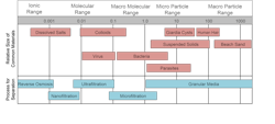
The emergence of the membrane technologies micro- and ultrafiltration at the end of the last century and into the 2000s gave water treatment engineers an alternative method for suspended solids removal in many applications. Figure 2 outlines the filtration ranges of common technologies.
MF and especially UF can greatly increase protection of RO membranes from particulate fouling. The results have been so impressive that the arrangement below has become common for makeup water treatment in the combined cycle power generation industry.

These modern systems do not require a full ion exchange system but rather a simpler mixed-bed or electrodeionization unit that “polishes” the RO effluent. Common is for a vendor to supply portable mixed-bed “bottles.” When a unit reaches exhaustion, plant personnel can connect a new bottle and have the vendor replace the exhausted unit and take it off-site for regeneration. This eliminates the handling of dangerous regenerant chemicals, plus the resin comes back fully regenerated, which is not typical with on-site regeneration.
Membrane configurations
Two UF configurations are prominent. In one, the membranes hang within a vessel(s) containing the raw water to be treated. Mild vacuum is applied at one end of the membranes to pull water through the material leaving particulates behind. The popular alternative is a pressure-vessel design.
Unlike the spiral-wound membranes in RO systems, the pressure vessels in UF units contain thousands of spaghetti-like hollow fiber membranes.
The UF process operates via a combination of crossflow and dead-end filtration, in which the raw water flows parallel to the membrane surface, with water passing through the membranes during passage. The purified stream is known as permeate. Most particulates remain in a small “reject” stream that exits separately from the system. An outside-in water flow through the membranes is more common, but inside-out is also possible.
UF membrane pore sizes are larger than those of RO membranes, and thus the driving force to move water through the membranes is much lower than for RO. The differential pressure is commonly termed the transmembrane pressure (TMP), which is further examined below.
Some particulates collect on the membranes, and these must be removed to prevent fouling. Standard is a short (one minute is common) burst of reverse water flow accompanied by an air scour. The process initiates at timed intervals of perhaps 20-minutes or some similar frequency. (The frequency is adjustable to allow operators to react to changing raw water conditions.) Modern units also have a chemically-enhanced backwash (CEB) feature that periodically injects acid, caustic or a chelant into the backwash water to help remove such foulants as organics and iron oxide particulates.
As good as these procedures are in keeping membranes clean on a day-to-day basis, they are not enough to ensure reliability over the long term, which brings us to a key point of this article.
A critical element: Clean-in-place
As author Buecker can attest from direct experience, a well-designed MF or UF may operate maintenance-free for long stretches. (Ask me about having to sweep cobwebs from a unit because it “hummed along” for months without any needed maintenance, or so my former power plant staff and I thought.) But as this aside suggests, one very important item should not be overlooked; that being periodic clean-in-place (CIP).
Modern UF control systems allow operators to monitor performance at the unit’s workstation and also on computer screens located in plant control rooms, labs or anywhere else in the facility. The following data and trends provide clues regarding cleaning needs:
- Rising TMP: A steady or sometimes rapid increase in TMP at constant inlet flow rate.
- Decreasing Permeability: Reduced filtrate flow or slower recovery after backwash cycles.
- Reduced Cleaning Efficiency: Air scour backwashes and CEBs no longer fully restore performance.
- Differential Pressure Changes: Sudden surges upwards may indicate particulate plugging or scaling.
Daily monitoring of these parameters by plant operators is important to prevent irreversible fouling. Better perhaps is a preventive maintenance approach with a regular CIP schedule, say every quarter or some similar period, to clean membranes before any of these trends become evident.
Figure 4 shows a cleaning cart that the plant’s maintenance department assembled per lab staff specifications. It could easily be moved to the makeup systems (and also to various auxiliary heat exchangers) when needed.
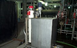
The wheeled cart includes a mixing tank, mixer and heater for warming solutions to increase cleaning efficiency.
Choosing correct CIP chemistries
The variability of potential foulants requires flexibility in cleaning chemistry. An incorrect choice can make a huge difference between quick recovery and persistent fouling. The following table provides important guidelines in this regard.
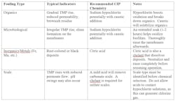
Note: Unlike most modern RO membranes that are attacked by chlorine, MF and UF membranes are fabricated from different materials, some of which are quite resistant to oxidizing biocides. Continuous biocide feed ahead of the unit will help to control microbiological fouling. However, any residual oxidizer must be removed upstream of the RO. A popular arrangement is sodium bisulfite (NaHSO3) feed immediately ahead of the RO unit to remove chlorine but protect against re-emergence of microbes that survived chlorination.
Leak testing
Even a clean system can underperform if the UF fibers are damaged or compromised. Over time, numerous factors including normal operation, chemical exposure or handling during maintenance can induce fiber breaks, pinhole leaks or seal damage. Integrity testing ensures that the unit still provides reliable performance and that any changes in filtrate quality are from fouling, not leaks. The “Pressure Decay Test (PDT)” is the most common integrity test. The filtrate (permeate) side is pressurized and isolated, with monitoring of pressure over the next several hours. A stable reading indicates that fibers are intact, but pressure loss, especially if it is rapid, suggests fiber breakage or another form of damage. Modern control systems can perform PDTs. Tests are important:
- After each full CIP or extended unit shutdown.
- Following any maintenance that involves the membranes and pressure vessels.
- If rapid changes occur in filtrate turbidity. UF systems are typically equipped with a continuous online filtrate turbidity meter that allows instant evaluation of conditions.
- If TMP or permeability suddenly fluctuate.
Maintaining fiber health
Modern control systems do an excellent job of regulating water flows and pressure during startup and shutdown and also controlling air scour flow rates that could otherwise cause membrane stress and fatigue. However, important operator/maintenance practices include:
- Follow supplier recommendations and use only approved chemicals in proper concentrations for CIPs. Failure to do so can weaken or damage membranes.
- Inspect potting and seals for cracks or damage that could allow bypass.
- Handle modules gently during installation, cleaning and removal to prevent physical damage.
The data acquisition system of a well-designed UF unit can guide operators to the location of a fiber leak. A common practice, for which repair kits are available, is to “pin” the individual fiber and stop flow through it. Occasional fiber pinning is a minor issue because it is one of many thousands of membranes. Maintaining a log of integrity test results can help to identify problem locations early on.
Conclusion
UF and MF have become very popular for particulate removal upstream of RO systems. But like all water treatment equipment, the units require conscientious monitoring to ensure long-term reliability. A point to note is that these membrane-based filtration processes are not confined to high-purity makeup applications. Reference 2 is a case in point, which highlights the use of UF in wastewater treatment at a steel mill.
In the design phase of these or any other water treatment projects, thorough analyses of the source water are critical for evaluating applicability.3 For UF or MF, a prime example is where river water will serve as the plant’s primary makeup source. Heavy precipitation may cause a huge spike in suspended solids concentration, which can potentially overwhelm the membranes for a period of time until conditions settle.
References
1. W. Byrne, Reverse Osmosis: A Practical Guide for Industrial Users, Tall Oaks Publishing, Littleton, Colorado, 2002.
2. Case Study: UF Wastewater Treatment Solution for a Steel Mill - SAMCO Technologies
3. Designing a Water Treatment Plant: What to expect - SAMCO Technologies
About the Author

Brad Buecker
Brad Buecker currently serves as Senior Technical Consultant with SAMCO Technologies. He is also the owner of Buecker & Associates, LLC, which provides independent technical writing/marketing services. Buecker has many years of experience in or supporting the power industry, much of it in steam generation chemistry, water treatment, air quality control and results engineering positions with City Water, Light & Power (Springfield, Illinois) and Kansas City Power & Light Company's (now Evergy) La Cygne, Kansas, station. Additionally, his background includes 11 years with two engineering firms, Burns & McDonnell and Kiewit, and he spent two years as acting water/wastewater supervisor at a chemical plant. Buecker has a B.S. in chemistry from Iowa State University with additional course work in fluid mechanics, energy and materials balances, and advanced inorganic chemistry. He has authored or co-authored over 300 articles for various technical trade magazines, and he has written three books on power plant chemistry and air pollution control. He is a member of the ACS, AIChE, AIST, ASME, AWT, CTI, and he is active with Power-Gen International, the Electric Utility & Cogeneration Chemistry Workshop, and the International Water Conference. He can be reached at [email protected] and [email protected].
Julia Biddle
Field Service Engineer with SAMCO Technologies
Julia Biddle is a Field Service Engineer with SAMCO Technologies, based in Herndon, Virginia. She has worked in the water treatment industry for eight years, including six years with SUEZ Water Technologies & Solutions and the past two years with SAMCO. Biddle commissions and provides technical field support for a wide range of water and wastewater treatment systems, including ultrafiltration (UF), reverse osmosis (RO), clarification, ion exchange, and dissolved air flotation (DAF). Her experience includes system commissioning, troubleshooting, pilot testing, and process optimization for industrial and municipal applications