Boiler Feedwater Pumps in Industrial Facilities
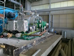
Boiler feedwater (BFW) pumps are an important part of many different industrial plants and facilities. These pumps are a special class of high-pressure centrifugal pumps used in many different models and sizes in many different plants, units, and production facilities. However, BFW pumps are not well-known by many engineers and operators. Too often, improper operation or mistakes in maintenance and repair due to lack of knowledge or experience have resulted in damages and serious problems.
Boiler Feedwater
High-purity BFW is required to ensure proper operation of any boiler or steam generation system. High-purity feedwater reduces the use of boiler chemicals due to less frequent blowdown requirements, reducing blowdown frequency by as much as a factor of 10 or 15. This results in lower fuel costs and better overall operation of boiler or steam generation systems. Scale build-up is reduced due to a smaller concentration of impurities in BFW to foul heat transfer surfaces. Fewer impurities also means reduced corrosion rates in all associated parts and components
Deposits decrease boiler efficiency and also result in premature failure of steam turbines and components of the steam system. Advanced water treatment methods such as multistage reverse osmosis (RO), ultrafiltration (UF), and others can remove greater than 99 percent of harmful traces and impurities. Therefore, these advanced methods should be used for BFW treatment.
Drivers for BFW Pumps
Steam turbine-driven BFW pumps are commonly specified and used in many plants. High-quality steam turbine drivers are more reliable and better than electric motors for high-speed applications of BFW pumps. Also, such steam-driven pumps would consume the steam the boiler or steam generation system produced. Therefore, it is more efficient and more suitable. Overall mechanical and control of steam turbine drivers will be simpler and better. However, electric motor-driven BFW pumps are still needed for start-up and also as back up and standby. Electrical motor drivers can be started faster than steam turbine driven ones. Therefore, these options are far better for standby and spare pump trains.
Usually the same model of BFW pump is used both in electric-driven and steam-driven BFW pumps in any application to encourage commonality and ease of operation and maintenance. For example, in a steam generation system, a 100 percent steam turbine-driven BFW pump is provided for normal operation and two 100 percent electric motor-driven pumps are provided for start-up, back up, and standby. Overall, a 300 percent installed capacity of BFW pump is provided. The required availability of this BFW pumping system is 100 percent.
As another example, in a critical, very large steam generation system, two 50 percent steam turbine-driven BFW pumps (total 100 percent) are provided for normal operation and three 50 percent electric motor-driven pumps (overall 150 percent) are furnished as back up, standby, etc. A 30 percent electric motor-driven BFW pump is used for start-up purposes. In this example, installed BFW pumps are 280 percent of the required BFW capacity. This provides 180 percent of spare and standby capacity. In addition to spare capacity, a 10 to 15 percent flow margin should also be considered for each BFW pumps.
Components & Subsystems
Casings for BFW pumps should be designed and manufactured to withstand the maximum working pressure to which it can be subjected. This should be assessed at most extreme conditions such as shutoff point at maximum speed (when the discharge valve is closed), failure of discharge non-return valve, obstruction of flow in the suction pipe or a combination of these, with hot water, cold water, and any possible thermal shocks without damage or leakage. The pump casing should be arranged to enable the removal of the internal assembly without disturbing the piping. Therefore, casing design, fabrication, and assembly should be considered with great care.
Many pumps use flange connections at both suction and discharge for the connection to the piping. However, for many BFW pumps, discharge flanges have been a source of leakage and trouble. In many small or medium BFW pumps, flanges of one or two pressure ratings above the calculated rating is often used to provide some margin and prevent leakage. However, this can be expensive and sometimes heavy and problematic. For high pressure and large BFW pumps, a flange connection at the discharge may not be feasible. This is particularly true if pressure and temperature are very high. This might also be valid for suction connection in certain cases. The connection between the pump casing and BFW piping at the discharge nozzle (or even sometimes both suction and discharge) is usually welded.
Corrosion and erosion have been reported as major issues for BFW pumps and, as such, great care is needed for the material selection. All areas subject to possible erosion should be protected by linings or an alternative protection method.
There are many other precautions in addition to material selection that should be considered for these pumps. Shafts of BFW pumps should be machined from high-quality forging of suitable grade stainless steel or alloy steel. They should be properly heat treated and grounded. Variable speed BFW pumps are widely used. As a target, the rotor should run without undue vibration at all speeds from zero up to 130 percent of rated speed.
Impellers are nearly always made of a suitable grade stainless steel or alloy steel, and should be of the shrouded type and fitted to the rotor shaft so it is readily removable and can ensure freedom from thermal distortion. Impellers are working at high speeds and high loadings. As these impellers are under considerable stresses, detailed stress analysis and fatigue calculations are required. Ideally, all impellers should have indefinite life or, alternatively, a useful lifetime of more than 100,000 hours. Each impeller and rotating part should be individually balanced. In addition, the rotor assembly should be dynamically balanced and the assembled rotor checked for concentricity and balance as well.
Journal bearings used for BFW pumps are usually advanced sleeve-type bearings, often tilting-pad bearings, with the exception of very small BFW pumps that might use rolling-element bearings. Provision should be made to permit vertical and horizontal adjustment of each bearing by shim manipulation. Return lubrication oil flow from each bearing should be visible and with local temperature indication. Bearings should be arranged so they are readily accessible and can be examined and replaced without removal of the rotor assembly from the pump.
High pressure BFW pumps need careful thrust (axial) force balancing. The axial thrust of the rotor assembly is usually balanced by a balancing device — often a drum-type balancing device. An alternative method of axial balancing is arranging the impellers in equally opposed groups, commonly known as back-to-back arrangements.
For modern BFW pumps, the complexity of pumps should be kept to a minimum, and fewer impellers with a drum-type balancing device are often popular. Even using these devices, however, there will be residual thrust (axial) force. This force should be accommodated by an external oil-lubricated tilting-pad thrust bearing. This thrust force should leave the rotor shaft in tension at all times to prevent shuttling of the rotor assembly and to avoid the instability of the lateral deflections involved with compressive loading of the shaft. The thrust (axial) bearing should be sized for all conceivable operating conditions, taking into account the wear of pump internals during the life of the BFW pump.
Fast and effective maintenance is a major requirement for BFW pumps. Cartridge designs for critical and maintenance-prone parts and subsystems are always encouraged. The goal is rapid replacement of cartridges for fast repair and maintenance. For rotating parts and rotor-associated subsystems, the method of replacement should not be dependent on free rotation of the shaft; the repair and replacement should be applicable in the case of shaft seizure or other malfunction cases.
Operation, Reliability & Service Conditions
BFW pumps should be properly and fully integrated with the steam generation system, boiler, and other surrounding facilities. Also, these pumps are often working in parallel and there are many dangers and risks associated with large high-pressure BFW pumps in parallel operation. In fact, many BFW pumps have failed because of the above-mentioned issues.
BFW pumps should have matched characteristics and should be capable of operating in parallel over the full operating range of the associated steam generation system. The overall configuration, driver sizing, and mode of operation should be such that when two or three BFW pumps are operating in parallel, failure of a running pump will not cause cascade tripping of the others. Key requirements include:
- Careful selection of the BFW pump and its performance curve
- Sufficient size of the driver
If a BFW pump fails and trips, other BFW pumps will try to catch up and temporarily work at the right side of the performance curve. If a pump’s driver is not sized for this transient case, the driver would trip on high-voltage protection (for an electric motor driver) or high speed (for a steam turbine driver). This is just a simplified example; all these cases should be properly studied, modeled and evaluated.
Another major challenge is that the boilers — or steam generation systems in general — should be able to work at part-load. Many boiler systems are designed to operate at 50 to 100 percent rated capacity. BFW pumps should be able to cope with this part-load operation. There is minimum safe flow through the pump below which a rapid temperature rise may occur. Therefore, a properly sized bypass line with bypass valves and other provisions should be considered to ensure safe and reliable operation of a BFW pump at part-load.
The failure of a check valve (non-return valve) at the discharge of a BFW pump could occur. This case would result in the reverse rotation of the pump. Such failures have been reported as these check valves are under severe operating conditions. BFW pumps should be capable of withstanding such malfunction without damage for a period of 10 to 25 minutes. An alarm is needed for such a malfunction case.
NPSH & Suction Conditions
There is a complex relationship between BFW pumps and the condensing subsystem of the steam cycle. In other words, a deaerator system is located at the suction of BFW pumps and operates at a pressure dictated by the pressure of the bled steam extracted from the steam system. This pressure affects the net positive suction head available (NPSHA) to BFW pumps. At part-load operation of the steam system, there is a risk that the pressure of the deaerator could drop significantly. Often a back-up steam supply is considered to come into operation to prevent the deaerator pressure from dropping significantly. However, in abnormal circumstances at start-up or low loads, the pressure of the deaerator may drop sharply, and the operation of BFW pumps should accommodate this case without risks of cavitation or damage.
Under conditions of sudden cessation of the steam supply to the deaerator (such as whole steam system or plant trip), a transitory drop in NPSHA at the suction of BFW pumps will occur. The NPSH margin (NPSHA-NPSHR) of BFW pumps should be enough, ideally more than the typical three or four meters, to deal with these situations. An ample margin is needed to deal with the worst transient conditions in the operation.
Warming Systems
A warming system should be provided for each BFW pump to avoid thermal shock at start-up. This warming system raises the temperature of a BFW pump in a controlled manner and keeps the pump warm and ready for start-up. There have been many different configurations for such warming systems, but the warming steam supply is nearly always used.