High-purity water treatment: Using membranes to protect membranes
An article in the July/August 2021 issue of Water Technology outlined important details regarding the production of high-purity steam generator makeup by ion exchange. Purified makeup is important for preventing corrosion and fouling in high-temperature steam generators. However, over the last several decades, many makeup systems have either been retrofitted or equipped up front with reverse osmosis (RO) for bulk deionization, followed by ion exchange polishing. A well-designed pretreatment system can help protect RO membranes from particulate fouling, among other issues. The development of micro- and ultrafiltration technologies (MF and UF, respectively) has been a boon in this regard. This article explores important details of MF and UF design and operation, and how a unit can further optimize makeup system performance.
RO preliminaries
During the heyday of large utility boiler construction and operation in the middle of the last century, the common method for high-purity water production was ion exchange (IX). A common IX configuration was cation-anion-mixed bed to produce makeup per the following guidelines:
- Sodium: ≤2 parts-per-billion (ppb)
- Silica: ≤10 ppb
- Specific conductivity: ≤0.1 µS/cm
But even freshwater supplies such as lakes or rivers usually contain several hundred parts-per-million (ppm) of dissolved ions. With ion exchange alone, IX resin beds exhaust rather rapidly and require frequent regeneration. This can be costly and sometimes disruptive to steady-state processes. The development of reliable RO technology offered a method to remove the bulk (99-plus%) of dissolved ions, thus greatly reducing the load on downstream polishing resins.
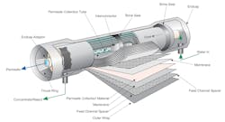
Proper pretreatment is an important aspect of reliable RO operation, particularly with respect to feedwater particulate control, as well as biological control. As Figure 1 illustrates, in the common spiral-wound configuration, a flat membrane sheet and supporting layers/spacers are all wrapped around a central, perforated plastic core. Feed enters the front end of each element and passes along the feedwater carrier while pressure pushes water through the membrane. The purified water, known as permeate, flows to the central core, while the increasingly concentrated feedwater (reject) exits the element.
Each RO pressure vessel typically has several elements arranged in a series.
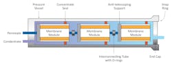
Brine seals can help prevent feedwater from short-circuiting the elements. A typical RO pressure vessel will have five or six elements.
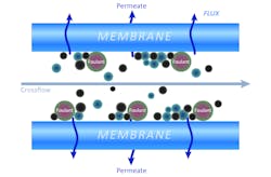
The configuration purifies water via the mechanism known as crossflow filtration.
The surface area of a modern spiral-wound RO membrane may be 400 square feet, and, as Figure 1 suggests, the tolerances are tight between the membrane and spacers. Accordingly, feedwater particulate reduction is an important aspect of minimizing RO fouling. Suspended solids usually accumulate in the lead membranes of an RO system, but it should be noted that dissolved ions concentrate as the water passes from one element to the next, increasing the scaling potential in downstream elements.
An important measurement for determining RO particulate fouling potential is the silt density index (SDI). Typical RO design has 10- or 5-micron (µm) cartridge filters upstream of the unit to remove particles. SDI tests may be performed on the effluent from these filters. A flowing sample of RO feed is passed through a 0.45-µm filter at 30 psig pressure. Measurement is taken of the time for 500 milliliters (mL) of water to pass through the filter at the beginning of the test (ti) and again after 15 minutes (tf). The SDI is calculated as shown below:
SDI15 = (1-(ti/tf))/T x 100
As an illustration, consider the following data taken from an operating RO unit:
ti = 34 seconds (s)
tf = 66 s
T = 15 minutes (min)
SDI15 = 3.2
A general rule of thumb is that SDI should be below 5, and preferably below 3, to protect the membranes. However, SDI may not be the only criterion that determines RO application suitability. The type of water and/or the nature of contaminants could be an important consideration. For instance, in one application, the SDI readings of the RO feed always ranged between 1 and 3. Yet the membranes fouled with very fine iron oxide particles.
RO feed particulate removal
Clarification followed by multimedia filtration was a common method for high-purity makeup pretreatment in the last century. Circular clarifiers with low rise rates of less than 1 gallon-per-minute per square foot of clarifier surface area (gpm/ft2) were a familiar sight. Because of the low rise rate, these units typically had a very large footprint. During steady-state operation, a well-designed clarifier-filter of this type could produce water with a turbidity at or below 0.5 nephelometric turbidity units (NTU). However, flow and temperature changes can induce upsets in clarifiers and cause filter fouling that could carry over to RO systems. Modern clarifier designs such as CoMag, Acti-Flo, and DensaDeg have much greater rise rates and can efficiently remove particulates in a significantly smaller unit.
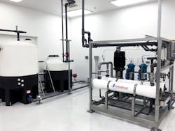
As an alternative or supplement to these advancements, the membrane technologies of micro- and ultrafiltration have demonstrated excellent results for particulate protection of RO membranes. To offer a brief case study: in the mid-2000s, one of the authors was involved in a project to replace an aging clarifier with a microfilter for RO pretreatment, in which the makeup system served a large, supercritical steam generator. This was an instance where RO had been retrofitted upstream of an existing IX demineralizer. The microfilter could operate for long periods without maintenance, except for a quarterly off-line chemical cleaning. Additional details are woven into the discussion below.
Hollow fiber membranes are typical for MF and UF design. Both pressurized and vacuum systems are available. Figures 4 outlines an example of a pressurized system.
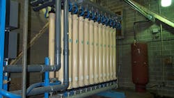
Figure 5 illustrates the filtration ranges of MF, UF, nanofiltration (NF) and RO. MF and UF are intended strictly for particulate filtration, whereas NF, and, of course, RO, remove dissolved ions.

Expanding upon the aforementioned case study: when the clarifier/media filter was swapped out for the microfilter, the turbidity of the RO feedwater dropped from a typical range of 0.3–1.0 NTU to less than 0.05 NTU, where it remained. Unfortunately, data from any SDI tests that might have been performed at the time no longer exist, but another indicator was available to show the improvement. Prior to the changeover, the plant chemistry technicians normally had to replace the RO cartridge filters every two to three weeks based on the increase in differential pressure as the filters accumulated solids. The cartridge filter replacement frequency decreased to once every two to three months following startup of the microfilter.
Modern pretreatment trends
The power industry has undergone significant changes, especially in the 21st century. Many coal-fired power plants have been shut down, and more are disappearing all the time. Replacements include renewables and natural gas-fired power. Many of the latter facilities are combined-cycle units, with a portion of the power coming from combustion turbines and the balance from steam turbines driven by heat recovery steam generators (HRSGs). Combined-cycle power generation has lower capital and operating costs and higher net efficiencies than coal plants; they are also able to start up and shut down quicker. These factors mean clarifier technology is not always a good fit. A very popular makeup treatment configuration for new combined cycle plants is shown in Figure 6.
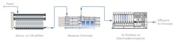
With respect to the polishing aspect of this design, portable, mixed-bed “bottles” are often selected. In this setup, an outside vendor removes a vessel at a pre-determined throughput and replaces the bottle with one containing fresh resin. Exhausted resin is regenerated off-site. It is common practice to have two bottles in a lead-lag arrangement, with the trailing unit moved forward and the fresh bottle placed in the tail position.
Protecting MF and UF systems
While MF and UF systems may be superb for protecting downstream RO membranes and can typically operate for long periods with little to no maintenance, some care may be required for system reliability.
MF/UF operates via what can be thought of as a combination of cross-flow and dead-end filtration, in which the raw water flows parallel to the membrane surface. Water that passes through the membranes is permeate, with a small fraction that flows along the surface to carry away many of the suspended solids. This reject water flows to waste.
Operating pressures for these systems may range from 10 to 40 psig, because, unlike RO, the membranes do not induce an osmotic pressure. However, during normal operation, particulates and microbes can accumulate in MF/UF membranes; regular flushing may be needed to mitigate irreversible fouling. A common example is permeate production for 20 minutes followed by a one-minute automatic backwash/air scour with return to permeate production in a continuously repeating pattern. Modern units typically include a periodic backwash with chemical treatment to help clean the membranes. If iron oxide particulates are the primary issue, citric acid may be very effective at both chelating and dissolving the iron. If organics are the problem, a mild caustic and/or bleach solution may be best. The typical membrane materials are polyvinylidene fluoride (PVDF) or polyestersulfone (PES).
Beyond backwash cleanings, some additional protection may be needed. A common recommendation is a quarterly (or some similar frequency) off-line cleaning with warm citric acid, followed by a rinse and warm caustic, or perhaps vice versa depending on the nature of foulants that might accumulate. This cleaning can often be performed in one shift.
Also, it is important to note that membranes can be sites for microbiological fouling. Although the microbes will not typically attack the PVDF material, formation of bacterial colonies can inhibit flow and may eventually cause irreversible fouling. Accordingly, a continuous dosage of an oxidizing biocide upstream of the unit is typically recommended to minimize microbiological fouling. Removing the oxidizer ahead of the RO is recommended to help mitigate membrane damage.
Please remember that each system is different and has unique treatment needs. Due diligence is necessary for determining the feasibility for utilizing the methods discussed in this article. Difficulties have arisen at some sites where the inlet water had impurities that reacted with pretreatment or backwash chemicals to produce foulants or scale-forming deposits. Always consult your equipment manuals and guides and contact a water treatment professional before making changes to your systems and treatment processes.
References
- AlGhamdi, A., “Production of High-Quality Demineralized Water for Steam Generation Units”; Water Technology, July/August 2021.
- Buecker, B., “Microfiltration: An Up and Coming Approach to Pre-Treatment for the Power Industry”; presented at the 26th Annual Electric Utility Chemistry Workshop, May 9-11, 2006, Champaign, Illinois.
Brad Buecker most recently served as senior technical publicist with ChemTreat, Inc. He has more than four decades of experience in or affiliated with the power and water treatment industries. He is a member of Water Technology's editorial advisory board. Brad is now president of Buecker & Associates, specializing in consulting and technical writing. He may be reached at [email protected].
Katie Perryman is manager of ChemTreat’s pretreatment technical team as well as the company’s Early Career Program. Her 8 year career at ChemTreat has focused on membrane separation and ion exchange with an emphasis on consulting on and troubleshooting pretreatment systems in different water treatment applications. Katie holds a B.S. in chemistry from Virginia Tech.
About the Author

Brad Buecker
Brad Buecker currently serves as Senior Technical Consultant with SAMCO Technologies. He is also the owner of Buecker & Associates, LLC, which provides independent technical writing/marketing services. Buecker has many years of experience in or supporting the power industry, much of it in steam generation chemistry, water treatment, air quality control and results engineering positions with City Water, Light & Power (Springfield, Illinois) and Kansas City Power & Light Company's (now Evergy) La Cygne, Kansas, station. Additionally, his background includes 11 years with two engineering firms, Burns & McDonnell and Kiewit, and he spent two years as acting water/wastewater supervisor at a chemical plant. Buecker has a B.S. in chemistry from Iowa State University with additional course work in fluid mechanics, energy and materials balances, and advanced inorganic chemistry. He has authored or co-authored over 300 articles for various technical trade magazines, and he has written three books on power plant chemistry and air pollution control. He is a member of the ACS, AIChE, AIST, ASME, AWT, CTI, and he is active with Power-Gen International, the Electric Utility & Cogeneration Chemistry Workshop, and the International Water Conference. He can be reached at [email protected] and [email protected].