Advanced Conductivity Measurement for Water Treatment Systems
By David M. Gray
Conductivity is the primary measurement of mineral contamination in water and has been in use for this purpose for well over a century. As an on-line measurement it provides inexpensive, reliable monitoring of water quality through the various stages of treatment. The technology for conductivity measurement has improved through many generations of analog and microprocessor-controlled measuring circuits and has greatly improved accuracy and temperature compensation.
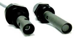
View of electrode spacing in conductivity sensors with 3/4" NPT process connection and cell constants of 0.1 cm-1 and 0.01 cm-1
A recent technology contribution further improves accuracy and increases rangeability by well over an order of magnitude. Taking advantage of the integration of the physical sensor with the measuring circuit in a compact package, the unified sensor overcomes limitations at both ends of the measurement spectrum. The same sensor can be used in both high purity water and in quite conductive waters up to seawater. Benefits of using a single, wide-range sensor for all stages of water treatment include savings in specification, procurement, installation, startup, training, maintenance and spare parts inventory.
Sensor enhancements also include on-board memory that stores and communicates complete sensor identification and calibration data to the readout instrument for simplified startup and calibration. This same capability is also available for related parameters of pH, ORP (oxidation-reduction potential) and dissolved oxygen.
Conductivity Measurement
When a voltage is applied to the two electrodes of a conductivity sensor immersed in a solution, ions between the electrodes are attracted to the oppositely charged electrode and move toward it as the current flow in the solution. (Current flow in the wiring is carried by electrons.) This current flow is used for the conductivity measurement. However, if the ion migration and electrochemical reaction at the electrode surfaces are significant, these effects will interfere with the conductivity measurement. These effects are often referred to as polarization.
To minimize polarization, AC voltage is always used for conductivity measurements. This changes the polarity of the electrodes frequently enough that ions don't move or react significantly. In addition, in state-of-the-art instrumentation, the voltage and/or frequency of the applied AC are selected by internal auto-ranging to achieve the optimum compromise between obtaining adequate signal and minimizing polarization and other interferences. This auto-ranging is invisible to the user.
The sensor cell constant, determined by the geometry of the electrodes, is another factor critical to the measurement. Lower conductivity measurements generally require a lower cell constant, with relatively large cross-sectional areas of solution and closer electrode spacing in order to obtain a good signal without having to measure too high a resistance.
Higher conductivity measurement generally requires sensors with higher cell constant. This means smaller cross-sectional areas of solution with higher current density and wider electrode spacing to prevent having to measure too low a resistance. The exact cell constant requirements for a particular range depend also on the measuring circuit, the cable and the surface condition of the electrodes. An integrated measuring system is required to assure achieving specified performance across the entire measurement range.
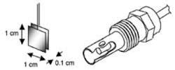
Parallel plate sensor with cell constant = length (0.1 cm) / area (1 cm2) = 0.1 cm-1 and a coaxial conductivity sensor with the same effective cell constant
Most process conductivity sensors in the low to moderate conductivity range now use the coaxial cell design with inner and outer electrodes which provides the same effective ratio as the easier to visualize parallel plate electrode design.
Previous work has detailed the determination of the precise cell constant with traceability to ASTM and NIST standards, how this has been incorporated into factory calibration facilities, and many other aspects of conductivity measurement.
Integral sensors are available for conductivity, pH/ORP and dissolved oxygen.
In real installations, the vulnerability to interference from both bubbles and particulate contamination is greatly reduced if the spacing between sensor electrodes can be made wider. In addition, wider spacing gives less flow restriction and faster response which can be important in deionizer rinse-down processes. Therefore there is an advantage to providing a measuring circuit that is capable of measuring pure water accurately with a higher cell constant.
Integrated sensors described here use a nominal 0.1 cm-1 cell constant for the full range, including very accurate ultrapure water measurements. Other instrumentation must use lower cell constants with more electrode surface area spaced more closely together. In some applications, the reliability of measurement can be improved significantly by using the higher cell constant but the measuring circuit must be able to accommodate it. Range specifications should be reviewed carefully.
Integrated Sensor Design
The UniCond™ conductivity sensor from Mettler-Toledo Thornton applies modern electronics and sophisticated measuring algorithms to the challenges of conductivity measurement. The sensor integrates the measuring circuit with the physical sensor into a single unit that also includes analog to digital conversion. It transmits a digital signal back to the readout instrumentation.
Integrated Conductivity Measurement -
An obvious advantage with integrating the sensor and measuring circuit is that the wiring distance from the electrodes to the measuring circuit is reduced to only 1 to 3 inches, all sealed within the sensor body. This is in contrast to traditional installations which must handle various lengths of analog signal cable, typically from 5 to 150 feet from sensor to transmitter. Of course it is still necessary to get the signal over that same distance but with the integrated sensor it is in a much more robust digital form.
With the very short and fixed analog signal wiring, the problems of cable capacitance are eliminated. Not only does this prevent errors at low conductivity where AC leakage through cable capacitance is a problem, but it also allows much closer control over measurement parameters.
Measurement frequency and voltage have fewer constraints. With much improved handling of polarization effects, the upper range of the conductivity sensor can be greatly expanded. With this technology the range of measurement has been pushed beyond previous limits so that a single integrated conductivity sensor can now measure accurately from ultrapure water up to 50,000 μS/cm using its comprehensive automatic internal auto-ranging.
Calibration Accuracy -
With traditional measuring systems, the sensor is factory calibrated separately from the transmitter measuring circuit and each is assigned an accuracy or limit of error. The two limits of error are added together to determine the worst case measurement error. In addition, there could be errors due to installation with very long cable, poor wiring practices or electrical interference. But with the integrated sensor, the sensor and measuring circuit are inseparable and they are factory calibrated as a system at the same time, resulting in a single limit of error, the same as a traditional analog sensor by itself. The digital readout instrument introduces zero error. The single factory calibration accuracy is the installed accuracy since there are no additional variables to degrade performance in the field.
Temperature Measurement -
Temperature compensation of conductivity is particularly important, especially in pure water ranges where the temperature coefficient can be as high as 7% of reading per degree C in cold deionized water. Naturally this requires a very accurate temperature measurement. In addition to having accurate factory temperature calibration, the elimination of analog signal cabling with the integrated sensor eliminates any variable wiring resistance in the temperature measuring circuit. Therefore, there is no degradation of the factory temperature calibration at installation since no cable resistance is added in the measurement.
Just like with conductivity, the factory temperature calibration is a system calibration, correcting for any errors in the measuring circuit and the sensor simultaneously. Therefore the temperature measurement and compensation is more accurate than with traditional instrumentation which has separate sensor and transmitter measuring circuit for temperature.
On-Board Memory -
Along with the measuring circuits, the integrated sensors include non-volatile digital memory. This memory maintains all identification, calibration and diagnostic data needed for operation and documentation. Such details as measurement parameter, part number, serial number, factory calibration data and date, user calibration data and date, and diagnostic factors are available to the readout instrument for immediate recognition as soon as the sensor is connected. A user does not need to calibrate or enter conductivity and temperature calibration constants to achieve rated accuracy at start up. The result is plug-and-measure functionality that greatly reduces the chance of operator error.
Application Implications
The ability to measure from ultrapure water to brackish waters up to 50,000 μS/cm with a single integrated conductivity sensor simplifies water treatment instrumentation. This remarkable rangeability covers all measurements of most water treatment systems so the sensor becomes universal. It allows very straightforward specification, documentation, installation, wiring, operation and planning for spare parts.
In cooling, recycle and reclaim waters as well as makeup water treatment, this single sensor design can eliminate a great deal of confusion. With conventional conductivity equipment, two or more sensors with different cell constants are needed to cover the range from recycled or brackish raw waters through the purification stages to pure water. The integral sensor eliminates questions about what cell constant to use, what calibration data to enter, what spare parts to maintain and other decisions where multiple sensor types would normally be required. This greatly improves system simplicity and reliability.
Conclusion
This new development of integrated analytical measurement technology promises to improve the quality of measurements in many ways and is anticipated to receive wide industry acceptance in the next few years.
References
1. D. Gray, "A Comprehensive Look at Conductivity Measurement in Steam and Power Generation Waters," International Water Conference, Paper IWC-06-09, Engineers Society of Western Pennsylvania, Pittsburgh, PA, Oct 2006.
About the Author: David Gray is a Senior Product Manager at Mettler-Toledo Thornton, holds a B.S. in Chemical Engineering from Case Western Reserve University and has over 35 years experience in the design, application and marketing of process analytical and control instrumentation.
Editor's note: This article was based on a paper presented at the 71st Annual International Water Conference, sponsored by the Engineers Society of Western Pennsylvania, San Antonio, TX, October, 2010.
Past IWW Issues


