Guadalupe Hydroelectric Plant: Control Valve Is Key Cooling System Component
Case Study
The control valve combines precise flow control with flow metering to ensure stable pressure.
By Alejandro Duque and Patricio Egan
The Guadalupe IV Hydroelectric plant is located 70 km from the of city Medellin in the Antioquia Province of Colombia, and provides electricity to the surrounding areas of Medellin, Envigado and Guadalupe. It has a power generation capacity of 216 MW and a net capacity of 202 MW. The power plant delivers 1,205 GWh per year, with a net generation of 1,026 GWh per year to the Colombian Power Network.
There are three Francis Vertical Shaft Turbines, with two of the units generating 67 MW and one unit generating 68 MW. The cooling system for the three turbines collects water from a 235.3-cubic-meter holding tank. Because the water has already been used by the turbines, it contains fine sand particles. If any sand were to come into contact with the turbine bearings, it would be extremely problematic so the water is filtered through screens (1 mm openings) before it is used for cooling.
The sand is essentially decanted in the bottom of the tank and can get up to 30 cm high in a period of six months with normal operation. This gradually decreases the efficiency of the cooling system due to obstructions caused by the suction of sludge.
The hydroelectric plant was faced with suspending the operation of its generators for a period of up to two days because of the rudimentary drainage systems to remove the sludge at the bottom of the tank.
Plant engineer Santiago Ramirez and operations director Carlos Ospina designed a sludge removal system that would not only do a better job but significantly reduce the downtime of power generating operations. They did this by designing a network of high-pressure sprinklers that are installed on the bottom of the tank and fed with pressurized water. The high-pressure sprinklers stir the sludge in the bottom slab of the cooling tank, and through a submersible pump they discharge the muddy water into the river at one side of the powerhouse.
To ensure that the pressurized water flows into the tank at a constant 150 L/s (2,377.5 US GPM), they needed to install a control valve to regulate the flow. The inlet for the pressurized water comes through a 2-inch stainless steel pipe (AISI 304) installed upstream of the intake valves of the generators. This gives a static pressure of 40 bar (580 psi) that feeds into a 6-inch main pipe feeding into a grid of 110 PVC high-pressure sprinklers in the bottom of the tank. With a stable flow and pressure, the sprinklers are able to stir up the sludge for removal from the bottom of the tank.
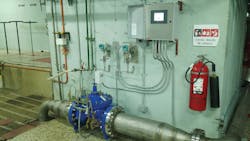
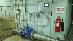
The Singer 10” 206-2SC-MV Class 300 control valve was chosen because it combines precise flow control with flow metering to ensure that the flow is adjusted to supply 150 L/s of water at stable pressure. This hydraulically operated valve introduces or releases water from the control chamber above the diaphragm to effectively maintain accurate water control. The metering valve (MV) calculates the flow rate through the valve using a proprietary algorithm, the position of the valve and the pressure differential across the valve. The calculated flow rate can be used as a feedback value to the controller to automatically manage the flow control.
Sludge removal is now performed approximately every six months. The plant is only out of service for six hours to prevent the stirred solids from being pumped into the cooling system.
The installation of the sludge extraction system involved assembling the ejectors grid in the bottom of the tank and then connecting the whole system to the flow control valve. The control valve was installed on the top of the tank, leaving a straight stainless-steel pipe stub upstream with a length of four times the valve’s flange size to ensure stable flow across the valve. The hydroelectric plant needed to shut down for five days to complete the installation.
Sludge removal is now performed approximately every six months. The plant is only out of service for six hours to prevent the stirred solids from being pumped into the cooling system. The operation consists of lowering the water level of the cooling tank, starting the submersible pumps and operating the flow control valve to initiate the agitation of the decanted solids before discharging into the river.
With the commissioning of the sludge extraction system several benefits were achieved. The cleaning process has changed from a manual one using approximately ten people to an automatic process with only four people. Cleaning the tank used to take 26 hours; now it takes only six, and downtime for maintenance of the generators has been reduced as the quality of the water in the cooling system has significantly improved.
“By regulating the flow with Singer’s control valve in our new sludge extraction system, we have reduced our maintenance costs and reduced necessary interruption time of power generation,” said Ospina. “We are very pleased with this outcome and the stability performance of the valve.”
The cooling tank is also connected to the plant’s firefighting system, so having this guaranteed water pressure from the control valve for a high-demand situation is a vital safety requirement for the plant. IWW
About the Authors: Alejandro Duque is the customer relations manager for Singer Valve. He has a degree in mechanical engineering and has worked in the valve industry for over 25 years. Patricio Egan is Singer Valve’s area manager for Latin America, Spain and Portugal. He holds a mechanical engineering degree and has amassed over 40 years of mechanical, hydraulic and hydrodynamic expertise.

