ZLD Today, Part 2: What to Do with the Water
by William E. Moore and Timothy J. Rittof
• Part 1 of this series discussed power generation design and source water character. Here, we review major constituents for consideration - scale formers, concrete and metal corrosive agents, and biological food sources - in designing treatment processes
Test the water we must. For now, let us consider a few samples of water supplies to power generating stations.
What we hope to have as all of our water sources is water with soluble salts as our only limitations. Little alkalinity, hardness or silica can be found. Limits on cooling tower cycles will be:
- Total solids concentration
- Chloride, depending on choice of condenser and piping materials
- Sulfate depending on choice of concrete for the tower or basin
Water with alkalinity and both calcium and magnesium hardness as major contributors and low silica can be treated in a number of ways. If the station isn’t designed for zero liquid discharge (ZLD), we can use sulfuric acid along with scale inhibitors and dispersants to deal with alkalinity and hardness. Concentration cycles could be limited by total solids, silica, or gypsum. If it is a ZLD station, raw water softening becomes very attractive. If alkalinity concentration is greater than or equal to calcium hardness only cold lime softening is required. Soda ash isn’t required and the total solids of the supply are reduced. Silica removal can be augmented by magnesium chloride or magnesium sulfate addition.
In a typical municipal reclaim water, alkalinity is a major contributor; calcium hardness is significant but magnesium hardness is minor. Silica may or may not be significant. Softening will be useful and valuable for these waters but can be either raw supply or side stream. The determining factor will be the total solids limit in the cooling tower design:
- If less than 7,500 mg/L, then side stream can be considered.
- If less than 3,000 mg/L, side stream should be considered. In some instances, side stream weak acid cation (WAC) exchange will provide both the hardness and the alkalinity removal most economically.
The “average” water quality is the source of the most interesting discussions among designers. Some justification can be made for any one of the above influent and effluent treatment techniques. Raw water softening may need soda ash addition (the additional magnesium needs more lime which needs more carbonate). Usually, the task is for the design engineer to produce a water that the cooling tower chemical supplier can economically treat to keep the circulating water from scaling at the desired concentration cycles.
Variations: We have one more composition feature to consider - variability. The power train will have a design case and multiple performance evaluation cases that are substantially different. The source water will have an average composition and a range of concentrations that are substantially different. A well source in California averages 10 mg/L calcium but may have over three times that for extended periods. A river source in New South Wales, Australia, averages 8.5 mg/L silica but has up to 19 mg/L for four-week periods. The picture is further complicated by alternative water sources with different compositions.
Circulating Water Estimation
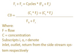
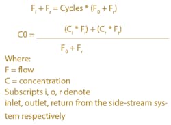
Graphs and plots will give us quick guidelines for assessment and help with presentation of conclusions, but there is no substitute for calculation. And the first part of the calculation is to set the boundary conditions.
Without side stream processing, the calculation is direct. With side stream treatment or water recovery, a little more work is needed.
null
The trick, if we can call it a trick, is in determining what the concentration in the return stream (Cr) will be. The reason for this is the operation of the cooling tower.
Water isn’t the only chemical added to the cooling tower - we routinely dose a cook’s list of additives to the cooling tower. And these additives do their job. Antiscalants chelate calcium, iron phosphate, and others to keep them soluble. Dispersants keep the size of precipitant particles small and keep them suspended. These additives are soluble in the circulating water and remain in the blowdown continuing to work after the cooling tower - in condensers (good) and in softeners (not so good).
Left out of this discussion, and worthy of lengthy additional discussion, is the impact and treatment of nitrogen and phosphorus. The first impact of nitrogen, as nitrate, is on the final ZLD step. Nitrate compounds, such as sodium, potassium or magnesium nitrate, are very soluble in water. At 100°C, a kg of water can dissolve 1.8 kg of sodium nitrate. The payment we make for this solubility is boiling-point rise (BPR). The solution of 1.8 kg NaNO3 in 1 kg H2O will not boil until 123°C (250°F) at atmospheric pressure. Mechanical vapor recompression (MVR) equipment isn’t appropriate to overcome this BPR. Direct steam use is required.
The second impact is that these components aid and abet biological growth, whether in water storage before the cooling tower, in the cooling tower, or in wastewater storage after the cooling tower. Nothing good will come of biological growth in cooling water. The cooling tower will be subject to additional corrosion and mechanical stress. Interference with heat transfer performance may limit power generating capacity. The organics are transferred to the ZLD system where they can interfere with settling in a softener, continue to grow on membranes, get cooked and steam distilled in the evaporator or get further cooked and make a meringue in the crystallizer.
Water Process
Pre-treatment comes in a few varieties - desalination, clarification, softening, and filtration. Two techniques relatively new to the United States are multistage flash (MSF) evaporators used widely in the Mediterranean and Caribbean, and ACTIFLO® ballasted floc clarifiers.
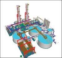
Post-treatment to provide ZLD will always end with evaporation and crystallization. Fortunate site selection sometimes allows solar evaporation in a “mono-fill” pond. But even with ponds, evaporators may be economically applied to reduce the size (cost) of the required evaporation pond. Figure 3 shows a 3-D model of a system at one operating station. The system employs raw water softening, wastewater evaporation, and evaporation pond solids disposal (see Figure 3).
The biggest question in selecting the evaporator is how big it needs to be. Can we use preconcentration with RO? Clearly the answer is “yes.” Should we? If the total wastewater flow is less than 200 gpm (1 ML/day), probably not. If the cooling tower cycles limit the total solids to less than 6,000 mg/L, probably yes. If less than 4,000 mg/L, almost certainly yes. To use RO concentration, we must soften the water to prevent calcium carbonate, sulfate or phosphate and silica or magnesium silicate scaling. This is where tower chemicals interfere. They also interfere with chemical, RO and ion exchange softening. RO concentration can save significant capital and energy costs - but it does so at the cost of eternal vigilance. The variability in water demand and composition discussed above will require monitoring and adjusting - that requires staffing.
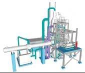
And we end with the crystallizer (see Figure 4), which evaporates remaining water away. It’s often physically the smallest of the pieces of equipment needed in the ZLD train, but not the least expensive. Here, we concentrate until we’re forced to stop. And all of the trace constituents that we didn’t or couldn’t measure in the water supply are concentrated as far as they can be. Also concentrated are all of those constituents we didn’t worry about when we added them to the cooling water or the boiler.
Problem Components
We’ll summarize with a short list of problem components for the ZLD design in Table 3.
Conclusion
It should be obvious from the abbreviated discussion presented here that defining a zero liquid discharge system requires a lot of discussion and study. If a ZLD system is required, it’s strongly recommended an engineer with experience and spreadsheets capability be hired for the study. In addition, there are a limited number of manufacturers who also can help find the most economic solution and produce the equipment. Anyone considering a ZLD system should schedule four months for studies, two months for bidding and purchasing and 14 months for delivery after ordering.
About the Authors: William E. Moore is a senior water treatment specialist at Calpine Corp. of Houston, TX. Timothy J. Rittof is a senior technical fellow at HPD, a Veolia Water Solutions & Technologies company based in Plainfield, IL. This two-part series is based on a paper presented at the 66th International Water Conference in Orlando, FL, in October 2005. Contact: 800-927-0319 or [email protected]


