Cooling tower filtration: Methods and procedures to obtain successful results
The importance for water filtration can be expanded into industrial applications where small orifices need protection from plugging or heat transfer equipment that requires protection from fouling. Such a need was brought to the attention of Orival Filters by Argos Cement Co. located in Newberry, Florida.
Producing cement is a dusty activity due to piles of materials affected by wind currents and conveyor belt systems transporting raw goods to various buildings for processing. For those not familiar with cooling towers, then the best way to describe them is as a large vacuum cleaner that uses air to cool water. The airborne dust is drawn into the cooling tower and becomes entrained within the cooling water.
Open cooling systems are composed of a cooling tower, a basin, pumps and a heat source. A cooling tower is an enclosed device using air to cool water by evaporation; thus, the atmosphere becomes the heat sink. Cooling towers are generally of two basic types: natural draft and mechanical draft. The former depends upon natural atmospheric conditions to move air through the tower, while the latter uses mechanical fans to move air through the tower. Mechanical draft can be either forced-draft design, where air is pushed through the tower by fans located near the incoming air, or induced-draft design where air is pulled through the tower by fans placed where the air exits the tower.
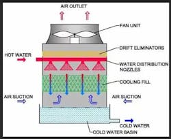
The basin is generally located beneath the cooling tower to catch and contain the cooled water accommodating liquid expansion/contraction, serving as a reservoir for the storage of surplus water, and to act as the sump for the cooling system pumps. The pumps circulate cooled water to the heat source where heat is absorbed. The water heads back to the cooling tower where the heat is transferred to the atmosphere.
The energy exchange is often accomplished by direct contact between the water and the source of heat, for example, when hot steel is cooled during the rolling process by being sprayed directly with the cooling water. Another means of removing heat from the source is by the exchange of heat energy across a solid medium such as in a heat exchanger. Here, another liquid in a closed system transfers the heat energy from the source to the cooling water by conduction through metal plates or the thin walls of metal tubes. No physical mixing occurs between the water in the open cooling system and the liquid in the closed loop system.
Customer interview
The importance of interviewing the customer is to gain full comprehension of the issues and the plant operating protocols. This first step cannot be stressed enough. Ask yourself, how can I prevent a catastrophic event from occurring with a piece of equipment that will be recommended for this application? Additionally, during this Argos interview, it was discovered that two installed sand separators did not perform adequately in removing the fine particles and caused an unnecessary pressure drop. Sand separators, hydro-cyclones and centrifuges spin water, creating a centrifugal force separating suspended solids heavier than water to be removed. In addition, the customer disclosed that the flow rate through the system varied due to the cooling water demand inside the plant; cyclonic separators work best with a constant flow rate
Due to the variations in flow and the required filtration degree of 50-micron, it was decided to select a different technology. That technology consists of a self-adjusting cleaning nozzle that impinges on the surface of a multilayer screen element. A vacuum is created at the nozzle tip removing the collected debris (filter cake) on the screen element surface.
Newer technology
Automatic self-cleaning screen filters are relatively new compared to cyclonic separators and sand media filters. Over the past three to four decades several manufacturers have developed automatic screen filters for the removal of suspended solids from pressurized water streams. Woven-wire technology has provided screens with maximum open areas and filtration degrees down to 10 microns. These screens provide a two-dimensional discrete opening, particles are positively removed based on size alone and no other characteristics such as specific gravity, shape or particle plasticity. This makes screen filters a good choice for the protection of orifices in full flow situations. Automatic self-cleaning screen filters remove organic and inorganic particles with equal efficiency. The removal efficiency is not dependent upon a probability function but is positive in nature. The pressure drop across the filter stays between 0.07 and 0.14 bars (1 and 2 psi) most of the time with maximum drops reaching 0.5 bars (7 psi) across the screen very briefly before initiating the automatic cleaning cycle. This can be an adjustable parameter for those existing applications with sensitive equipment losses.
The filter remains online and filtering during the entire cleaning cycle which takes 12- 40 seconds to complete. The total volume of water used for cleaning is quite small, usually <1% of total flow.

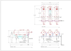
As seen in Figure 2D when the rinse valve opens to the atmosphere, a low-pressure area is created at the nozzle tip of the dirt collector, creating a high velocity vacuum. Simply, the difference between the higher pressure inside the housing of the filter and the atmosphere causes this effect. This concept is expanded further in Figure 3D with multiple nozzles. The dirt collector assembly is then moved across the entire surface in a spiral rotation of the filter element for a 100% cleaning.

Preliminary filter system sizing
The proper filter selection and design procedure is a multistep process. As previously mentioned, interviewing the customer with a broad array of questions mitigates any potential missteps in a design-build application. Basically, more information is better.
There are no shortcuts, and quite often there is a tendency to look at filter equipment literature and select something that matches the existing size of the application thinking it will work. This approach is a recipe for disaster.
Filter pipe connection sizes have nothing to do with proper filtration sizing
Filter housing pipe connection sizes are a means of convenience to connect the device to a piping system — nothing more.
Establishing the operating parameters is the first step. The customer should convey within a good degree of accuracy: the flow rate, operating pressure, electrical power availability and required filtration degree. Of these parameters, the filtration degree is the most important to establish the flux rate, meaning the volume of water that can pass through a square inch of filtration area per time unit; in this case we are using minutes.
The most difficult variable to accurately acquire is the TSS (total suspended solids), and particle size distribution, which is the amount of material that needs to be removed per liter of water at the established filtration degree. The contamination entering a cooling tower can vary greatly depending on the environmental conditions of wind movement and the concentration of dust, pollen and organic matter floating in the air. Water lab testing of samples from the circulating pump discharge is the only way to get a homogenous precision of what the system is generating. Even for that exercise, it must be realized that the lab sample is only a brief snapshot of water passing through the pump, however it is a starting point for the water quality evaluation.
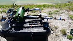
Once the water sample tests are complete, an onsite pilot test is conducted to confirm the flux rate. A pilot filter is just a miniature version of the full-size equipment, and is provided with a flow meter and pressure gauges. There is also a selection of filter elements of various micron ratings that can be easily changed out for particle removal trending and monitoring. Typically, 1-3 hours is required to establish the flux rate, then a redundancy factor will need to be considered
The scale of the full-size filter system is established from the flux rate. The design flow capacity is then divided up with multiple filter units in parallel flow. Multiple filter units installed in a parallel flow configuration are hydraulically equal, meaning they load or collect suspended solids at the same rate. When the system reaches a pressure differential setpoint, each will sequentially clean itself one at a time. The cleaning cycle is short, taking anywhere from 15 seconds to 1 minute per filter unit.
For the Argos project, each filter unit required 20-30 seconds for cleaning with no interruption of flow during the entire cycle.
Another design feature considered was for maintenance, whereby a single filter unit could be taken offline, and the system could still operate at full flow capacity without causing a plant shutdown. Additionally, if for some reason the entire filter system was to shut down, then an automatic bypass valve would open allowing cooling water to still flow into the plant. The final design step would be to determine the allowable footprint size of the filtration system and the amount of space necessary for maintenance. I have seen filter systems installed in small rooms without any consideration for future expansion, or disassembly by maintenance personnel.
A full set of scale drawings should be prepared and presented to the customer. A review process is then conducted to be finalized by all the affected parties. Another matter is the installation logistics including size, weight, transport and clearances for onsite installation, scheduling and safety considerations. This approval process protects all and enforces a team effort goal of a successful installation.
The problem
Argos’ cooling tower engulfs airborne dust that mixes with the water being cooled. That dust is not only abrasive for water cooled bearings, but it also forms an insulating layer inside the heat exchanger systems, impeding proper heat transfer. Plant workers struggle to control the proper temperatures, affecting product quality. Heat exchangers need to be disassembled and manually cleaned out causing unscheduled shutdowns. Additional wear of pump impellers, housings, shafts and seals add to plant operating costs.
The solution
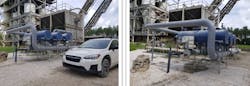
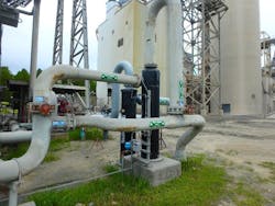
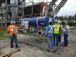
After the completed testing, Orival recommended three Model ORE/B-12-PX self-cleaning automatic filter units.
The results
Within one day of operation, the new filtration system started to provide relief from unscheduled shutdowns and maintenance emergencies. After two weeks it was decided to train the maintenance personnel on the operation and recommended maintenance. Within a few days after start-up, the fouling and cooling bearing issues were resolved.
Orival
About the Author
Stephen Fournier
Stephen Fournier is a consultant specializing in engineered water management systems, involving filtration, mechanical designs, hydraulic controls, treatments, and pumping systems. Originally from Massachusetts he moved to Florida in 1988 and started working for a small engineering firm designing irrigation systems for citrus groves. His skillset grew further by becoming a sales manager for an international filtration manufacturer for agriculture, industrial, and municipal markets. After 10 years in that position, he moved onto John Deere Green Tech as a district sales manager and the role of a product manager for filtration sales. He received an innovation award from John Deere for designing a specialized water recycling system. Steve moved on to become a sales manager for Orival Filtration systems for six years and now semiretired, works as a part time independent consultant.