New instrumentation eliminates rapid water pump cycling
Key Highlights
- A small municipal water utility experienced frequent pump shut off, without an obvious cause.
- The pump has a narrow dead band which is affected by the velocity head in the line, affecting a level sensing switch to the pump.
- A new control system will prevent rapid pump on-off cycling.

A small municipal water utility experienced frequent pump shut-off, requiring callout of a maintenance technician to reset the pump. Upon reset, no problems were observed, yet the pump would shut down shortly after the technician would leave the plant. Investigation revealed that inappropriate instruments controlled the process.
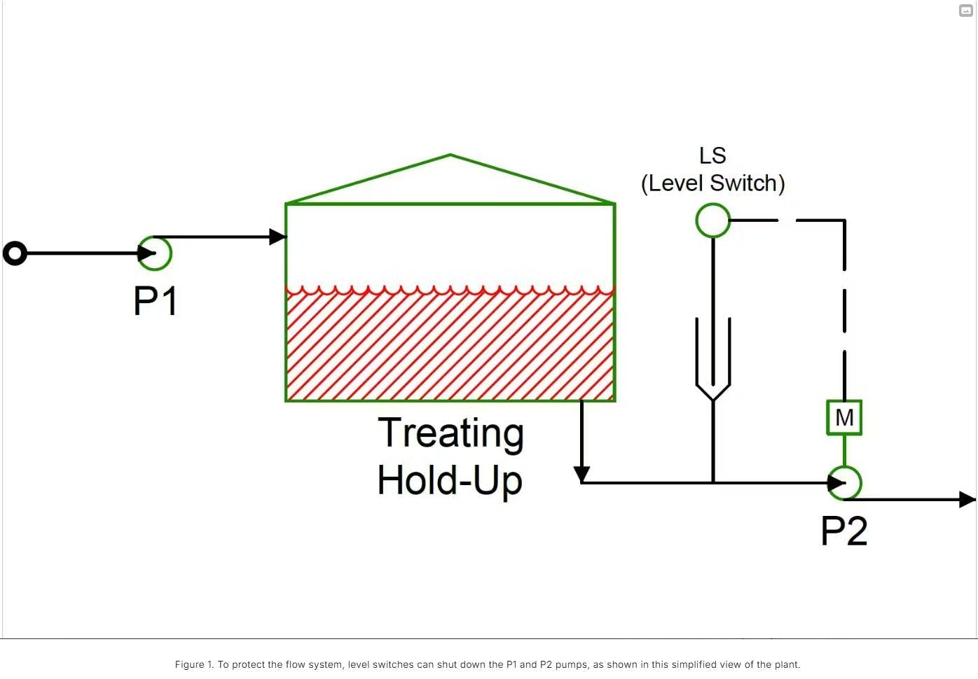
Fig. 1 shows the layout of the plant, where Pump P1 supplies water to a relatively small-volume tank and Pump P2 takes water from the tank and sends it to the water tower. A chlorination system for water treatment, not shown, surrounds the tank. To prevent chlorine release, pump P2 must remain under positive suction seal.
The tank has a roughly 36-min residence time between the usable high level and the usable low level. This plant routinely runs with minimal or no supervision. Part of the flow system has situations where pumps P1 and P2 run for 45 min simultaneously at nearly the same rates. Actual pump rates, however, will not be identical flow due to manufacturing and maintenance differences. Also, P2 rates vary with downstream pressure (height of water in the water tower), and P2 rates can be substantially higher than P1 rates, depending upon conditions.
Level switches can shut off P1 and P2 pumps to protect the system, and a low tank level switches off P2 (as shown in Fig. 1). A level switch on a pipe well installed on the P2 suction cuts electricity to the pump. When level rises, the switch trips a relay that turns the pump motor back on. Often, P2 cycles rapidly and eventually the motor control circuit trips P2 permanently to prevent motor damage. At this point, maintenance must come out and reset the pump motor.
By the time the maintenance technician arrives, the level in the tank has risen significantly due to P1 still running. Turning P2 on typically does not reveal any problems, and the level gradually drops in the treating tank, repeating the cycle.
The level switch (LS) acts as an on-off controller with a very narrow dead band. The height of water in the well cannot be directly observed, but the dead band is currently believed to be a few inches.
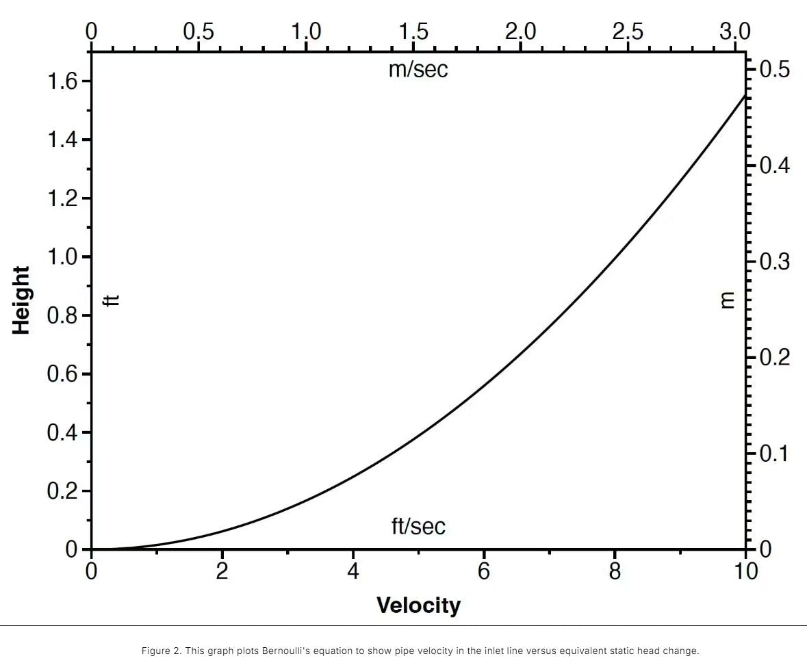
Normally a few inches of pressure difference in a system isn’t critical, but the narrow dead band is affected by the velocity head in the line. From Bernoulli’s principle, reducing velocity causes a rise in static pressure. When P2 shuts down, the level in the well increases. Fig. 2 plots pipe velocity in the inlet line versus equivalent static head change.
The normal operating condition is 2.84 ft/sec in the feed line. Fig. 2 shows this equivalent to a section head of 1.5 in. of fluid (0.125 ft). Although a few inches of fluid pressure drop does not affect operations, the level switch’s narrow on-off range is sensitive to as little as 3 in. of velocity head in the inlet. The sudden rise in liquid in the level measurement well due to velocity changes therefore causes rapid motor cycling at P2.
New level instruments are being installed, and the control system will have a dead-band added to prevent rapid P2 cycling.
The article referenced in this story originally ran as “Plant InSites: Why This Water Pump Kept Cycling Off” on Chemical Processing, an Endeavor Business Media partner site.