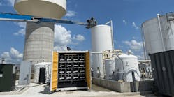
Reverse osmosis (RO) is a water purification process that removes impurities from water. Having clean water is essential for industrial applications. Boilers, pharmaceuticals, food and beverage and agriculture applications require pure water in their processes, and reverse osmosis is a common solution. To control the flow of water in these systems, valves are used. Depending on the complexity of the system, a variety of valves are used to accurately control the flow of the contaminated water purifying it into clean water.
The basics of osmosis and reverse osmosis
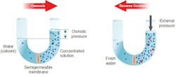
Osmosis is a naturally occurring phenomenon in nature when two solutions are separated by a semipermeable membrane. A semipermeable membrane allows certain molecules or ions to pass through it and prevents others from passing through — based on size and electrical charge. Figure 1 shows an example of freshwater (solvent) and salt water (concentrated solution). Naturally, the concentration of molecules attempts to equalize, which forces clean water through the semipermeable membrane to mix with the salt water. This force through the membrane is what is defined as the "osmotic pressure."
Figure 1. Osmosis and reverse osmosis diagram
In reverse osmosis, a system aims to move a concentrated solution, such as salt water, through the semipermeable membrane, which allows only the water molecules through and stops others. This effectively cleans and purifies the water. However, since this is not a natural phenomenon and the osmotic pressure is acting against the direction of desired water movement, there needs to be an external pressure to move the water in the desired direction. RO systems generally use pumps or gravity-fed water to accomplish this.
Industrial applications for RO systems
Certain industrial applications require water purity to have the same quality standards or even greater than potable drinking water. Oftentimes, these are continual systems treating large volumes of water operating at pressures between 100 psig and 1,000 psig. Depending on the required water quality after treatment, numerous membranes and passes can be used to increase effectiveness and decrease reject water volume. The following are examples of typical applications:
Boilers: Plants that use steam to drive turbines are often purifying their water before they boil it into steam. If contaminated water is turned into steam, it can damage the turbine blades, causing shutdowns and maintenance issues. This makes it more cost-effective to purify the water to increase the longevity of turbines.
Pharmaceuticals: To create consistent and pure products, pharmaceutical companies need pure water that is free of dissolved particles, bacteria and organics. Oftentimes, pharmaceutical products require dissolved particle levels to be up to 10,000 times lower than safe drinking water. RO systems in conjunction with other water treatment processes can be used to accomplish this.
Food and beverage: Purified water is needed to prevent health issues and to maintain production quality for food and beverages. RO systems are used in conjunction with additional treatment systems to purify water to ensure a safe product and consistent taste and odor.
Agriculture: Irrigation water oftentimes does not need to be as pure as drinking water, but finding suitable water is still difficult. By taking water that is not potable and passing it through simple RO systems, the water is up to standards for agriculture even if it is not potable.
Reverse osmosis valve selection
Depending on the step within the RO system, different valves are used to accurately and safely control the flow. The functionality of the valve creates pros and cons for usage, making different valves optimally used at different steps.
Solenoid valve
A solenoid valve uses a plunger to open and close an orifice, which either prevents or allows the flow of a medium. This plunger opens and closes by moving up and down by the use of an electromagnetic field generated by a magnet. Depending on if the valve is normally closed or normally open, the valve will switch positions when power is applied or taken away. These valves have a quick reaction time.
Ball and butterfly valves
Ball and butterfly valves are usually manually controlled with a lever, but they can also be electrically or pneumatically controlled. A ball valve has a ball with a bore through it to prevent or allow flow through the ball depending on orientation. A butterfly valve uses a thin disc, or wafer, that turns and opens to allow flow. These valves have good sealing properties.
Automatic shutoff valve
An automatic shutoff valve opens and closes based on pressure of the flow. It works in conjunction with valves downstream (i.e., a valve controlling flow into a tank) and can sense a closed flow downstream based on an increase in pressure, and it will then close. It operates mechanically and requires no electricity, saving energy and preventing lost water costs.
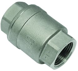
Figure 2. Check valve
Check valve
A check valve is a one-way valve. Generally, it is spring-operated, and when flow comes from the wrong side, the valve will close with the pressure to prevent flow. Figure 2 shows a check valve that can be threaded inline with the pipe.
Float valve
A float valve is used in a tank to shut off the incoming flow when it reaches a certain fill point. As the tank’s water increases, the float of the valve moves up, and it is connected to a lever that mechanically closes the valve. As the water level decreases, the float valve will then reopen.
Single-stage RO system
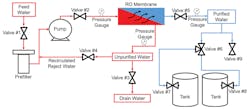
Depending on the purity needed and the incoming water quality, different purification steps can be in a series with RO systems. Looking at only the RO portion, Figure 3 shows an example of a single-stage system that recirculates the reject, or unpurified, water. Feedwater comes in and is pumped through the RO membrane, which separates the purified water from the unpurified. Industrial RO systems can be designed with multiple stages, and water passes through multiple membranes for better filtration, requiring additional valves to control the flow. Note: A single-stage RO system may have more or less valves than shown in Figure 3.
Figure 3. Example of an industrial single-stage RO system
Commonly used valves in RO systems
Feedwater valve
As feedwater comes into an industrial RO system, it will often go through an initial valve, as shown in Figure 3 as valve #1. This valve controls the flow of the contaminated water into the system and can isolate the system from pretreatment procedures or for maintenance purposes. Depending on the RO system sophistication, this could be a solenoid, ball or butterfly valve.
Automatic shutoff valve
After the contaminated water passes through the pump, it will often pass through an automatic shutoff valve, as shown in Figure 3 as valve #2. This valve is either controlled by monitoring the pressure or is a solenoid valve. A pressure-controlled valve will monitor the pressure on the output, and if it increases (a valve down the line is closed or something is preventing the flow), then it will close to prevent flow into the RO membrane. As pressure returns back to normal, it will reopen.
Reject drain valve
Figure 3 shows an option to recirculate reject water. Regardless of whether there is recirculation of reject water, there will still be reject water that will go to the drain. Oftentimes, this flow is monitored and controlled with a ball, butterfly or needle valve if precision flow control is needed. This valve can be seen in Figure 3 as valve #3.
Recirculated reject valve
If reject water is being recirculated, it will be monitored and controlled with a ball, butterfly or needle valve. In a multiple-stage or pass system, this water will go to additional RO membranes. This valve can be seen in Figure 3 as valve #4.
Check valve
A check valve is often located directly after the RO membrane to prevent any backflow through it. It can be seen in Figure 3 as valve #5. If there is a prevention of flow downstream by either a closed valve or pipe, then osmotic pressure will cause this purified water to travel back through the RO membrane, which could cause damage to the system. A simple check valve will prevent this, and it needs to be in place if an automatic shutoff valve is used.
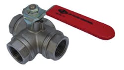
Figure 4. Three-way ball valve
Distribution valve
If the flow through the RO system is greater or less than the flow required in the industrial application, the purified water is often held in tanks. To distribute water to these tanks, a three-way ball valve (see Figure 4) can be used; it is also shown in Figure 3 as valve #6.
Float valve
To prevent overflow of a purified water tank, float valves are often used to ensure the tanks do not fill past two-thirds. They work in conjunction with automatic shutoff valves, because an overflow of water can be costly. This valve can be seen in Figure 3 as valve #7 and #8.
Sample valve
To monitor the purified water immediately after the RO membrane, a sampling valve can be in place to test the quality of the water. This can be seen in Figure 3 as valve #9, and it is often just a simple ball valve.
Valve material considerations
As RO systems handle contaminated feedwater (salt water, chloride-rich water, chemicals and ions, among others), corrosion can occur and degrade the valve’s seals and housing. It is important to know the environmental conditions and medium characteristics when choosing these materials to ensure longevity and proper functionality of the valve. Commonly, stainless steel valves are used on high-pressure systems, and PVC valves are used on lower-pressure systems.
