Hydraulic Overload Systems Provide Increased Protection for Clarifier Drives
By Jim Weidler
The incorporation of hydraulics into the overload system of clarifier and thickener drive units allows for improved torque monitoring and added protection for drive mechanisms.
The use of hydraulic overloads in clarifier and thickener drives is relatively new to the wastewater industry. The first applications were used in high torque industrial applications. However, the use of these systems for municipal clarifier and thickeners is gaining acceptance among end users and consulting engineers.
The typical mechanical clarifier drive includes a series of staged gear reductions, commonly referred to as primary, intermediate and final reducers. The primary unit is normally a worm or helical gear unit, commercially available from a number of gearbox manufacturers. The intermediate unit is available in an array of gear types including: planetary, helical, cycloidal or worm, with the most common being the latter. The final reduction, also know as the main gear, is typically a spur gear configuration.
The material of choice for the gear reducer housings has typically been cast iron, however, lower-cost fabricated steel housings were introduced into the industry in the mid to late 1970's and have been gaining acceptance. Both are commonly used in the industry today and normally include some style of mechanical overload device involving either rotation of the gearbox or lateral displacement of the internal gearing.
Mechanical Overload Systems
The mechanical overload system normally operates one of two ways, by either lateral displacement of the internal gearing or free rotation of the primary / intermediate gearbox.
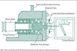
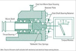
Lateral displacement overload systems are commonly used on clarifier drives that include a primary reducer, chain and sprocket set, intermediate reducer, and final spur gear set. The overload system is located on the intermediate gear reducer, normally a worm and worm gear set manufactured as an in-house product of the clarifier drive supplier. As torque is transmitted back through the drive, the input worm pinion is designed to displace laterally with resistance being created by a spring mechanism. (Figure 1)
The worm pinion displacement correlates to a specific torque load on the clarifier. The self-contained torque monitor device, housed in a NEMA 4X enclosure, contains a series of limit switches designed to close contacts and 1st indicate an "alarm" then 2nd "shut-off" the motor. As an option, the overload system can be provided with a 3rd safety device in the form of a mechanical "shear-pin" located on the driven sprocket. The pin is designed to shear, at a given torque value, if the electrical switches fail to engage.
The horizontal displacement of the worm shaft is very small, (+/-) 3/8", therefore there is a limited amount of actual needle movement on the torque gauge. The resulting torque reading can be misleading to the plant operators and does not provide an accurate assessment of the load on the clarifier rakes. It is important to note that these systems provide adequate protection to the clarifier and drive, as long as the overload system is properly set by the supplier and regularly maintained by plant personnel.
The "rotational reducer" type overload system was developed out of necessity. Since most commercially available gearbox units do not come equipped with integral overload devices, manufacturers were forced to develop some form of overload protection. By allowing the primary (and sometimes intermediate) gearbox to rotate under load the system can be designed to monitor torque loads on the clarifier.
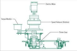
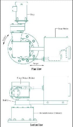
The rotational reducer system works under the same design principle as the lateral displacement system. As torque increases on the clarifier mechanism, it is transmitted back through the drive train and ultimately to the primary / intermediate reducer, which is free floating and allowed to rotate (Figure 2). As the reduction unit rotates, a plunger or rod is depressed and engages switches located inside the torque monitor (Figure 3).
As with the lateral displacement system, overload switches are set to 1st "alarm" and 2nd "shut-off". Some suppliers' designs lack the inclusion of a mechanical shear-pin, thus do not have a last resort safety device.
A common problem associated with rotational overload systems is a direct result of eccentric loads on the support bearings and gearing. Since the overload device is typically offset from the unit, the eccentric load is enhanced, which promotes premature wear of the intermediate gears / bearings. The net result is inaccurate gauge readings and potential failure of the entire overload system.
Hydraulic Overload Systems
Hydraulic systems may appear intimidating, but in reality they are quite simple, safe to operate and cost effective to maintain.
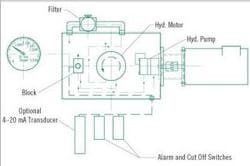
The hydraulic drive and overload system takes the place of the conventional primary gear reducer with a chain and sprocket set. The operational sequence (Figure 4) includes a standard C-face electric motor that is attached to a hydraulic pump. The pump outlet line is pressurized, typically <750 psi, and connects to a manifold /splitter block with integral pressure relief valve. The block has output lines that pass flow to the hydraulic motor, pressure switches and pressure gauge.
Torque is transferred to the intermediate gear reducer through the output shaft of the hydraulic motor. The hydraulic motor is specifically sized and selected for a desired output torque and speed. The hydraulic motor converts fluid power back into rotational shaft power at a lower speed and higher torque.
The overload protection system includes multiple pre-set pressure switches that 1st "alarm" and 2nd "shut-off" at the desired torque ratings, with an optional 4-20mA transmitter for remote monitoring of the system. In addition to the pressure switches, a pre-set pressure relief valve allows the drive to gradually stall without damage to rotating mechanism. The relief valve is designed to take the place of the mechanical shear-pin common on the mechanical systems.
Improved accuracy is a major advantage of the hydraulic overload design. The operating pressure of the hydraulic system is directly proportionate to the load on the mechanism rakes, so gauge readings are much more representative of loads being applied to the mechanism. Standard units include a 6" diameter gauge with a stainless steel body and a liquid filled cavity providing torque readings in actual ft-lbf or N-m.
Hi-Tech Environmental is one company offering hydraulic overload protection systems. To ensure a long service life of its system, the entire 10 gallon hydraulic reservoir, including all external piping, switches and fittings, is constructed from 304 stainless steel. All internal hydraulic components are commercially available at local distributors. The open design of the housing allows for accessibility of all the components, while also providing maximum heat dissipation of the hydraulic fluid.
Semi-annual oil changes are recommended and periodic replacement of the oil filter are the extent of the maintenance. A visual replacement indicator gauge located directly on the oil filter eliminates guessing by letting the operators know precisely when filter replacement is required. Food grade lubricants are available for potable water applications.
Conclusions
Mechanical overload systems, although widely accepted and utilized, are not necessarily the best technology. Consideration should be given to the numerous benefits of the technically advanced hydraulic overload system. If reduced maintenance, long service life and added protection to your clarifier and thickener drives are a primary concern, a hydraulic overload system would be a logical choice.
About the Author
Jim Weidler is Vice President of Sales for Hi-Tech Environmental, Inc. Hi-Tech is a manufacturer of water and wastewater treatment equipment. Products include a complete line of clarifier and thickener drives. Both mechanical and hydraulic overload systems are designed, manufactured and utilized by Hi-Tech. These comments and opinions are based on actual operating experiences.
