New Drip Trap Automatically Drains Piping
How many times have you given this assignment to your operators: Drain all drip traps every shift. Operators know the importance of draining the condensate from digester type waste treatment plant gas piping systems, an easily overlooked chore. A new electrically actuated drip trap is making this assignment obsolete and freeing more time for operators to perform other important plant functions.
Draining the drip traps in an anaerobic digester waste treatment plant removes condensate in the gas piping system. Regularly performing the chore prevents corrosion and "water hammer" damage in the pipes. Excess condensate will restrict the gas flow and increase the pressure drop in the system. If gas is reclaimed for energy it also is important to keep the gas as dry as possible. Drip traps installed at all low points in the horizontal piping runs will remove this condensation when drained regularly.
Two main types of drip traps are available to collect condensate, the manual (handle) type, and the automatic (float operated) type. Draining the condensate using the manual type drip trap requires an operator to rotate a handle to the drain position and then back to the normal condensate collect position.
The automatic (float type) operates by the raising of an internal float to open a needle valve. This allows the condensate to drain. Both types are designed so that going between the opened and closed drain position will not allow gas to escape from the gas piping system. The manual type requiring an operator to drain is used at most waste treatment plants.
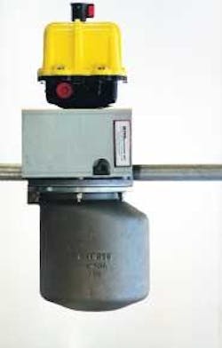
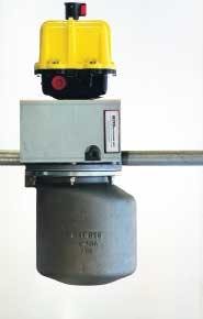
Failing to manually drain the condensate from the gas piping systems will cause problems of restricted gas flow, pressure drop and pipe corrosion. To eliminate these problems, BDS Systems Inc. has developed the Model 8460EADT Electrically Actuated Drip Trap using the Groth Model 8460 drip trap.
The 32-pound drip trap unit comes ready for installation and measures 23.5 by 11.5 by 9.5 inches. The unit has three main parts, the manually operated drip trap, an electric actuator with timer electronics, and a coupling assembly. The coupling assembly connects the actuator to the drip trap and houses the rotating handle assembly.
The timing unit is housed in the actuator and controls its operation. It controls the drain duration and drain cycles. Typically the drip trap is set to drain for about two minutes in every 12 hours.
The drain duration and drain cycles are field adjustable by DIP switches on the timing board. The timer electronics are adjustable in three-hour increments. The operator can set the timer electronics to adjust the time interval between drain cycles from three to 45 hours.
The coupling assembly mechanically connects the drip trap to the actuator, which rotates the drip trap's handle. The high torque type actuator is explosion-proof and suitable for installation in hazardous locations.
During a power outage the operator may access the drip trap handle by easily removing the coupling collar. This allows the operator to manually rotate the handle if a manual over-ride is necessary. A manual test button permits the operator to test the operation of the electrically operated drip trap between normal drain cycles.
The standard drip trap unit is designed for a five-psig maximum working pressure. Units are available for up to 60 psig. The condensate capacity is six quarts with an inlet and outlet connection of one inch.
An optional level sensing switch is available for applications in which a set draining cycle is not suitable. The sensor operates the drip trap whenever the trap reaches a full capacity. This accessory may be added even after the original installation. The level sensing switch consists of an RF type, 120V AC, 60 Hz unit. Its hardware consists of 304/316 stainless steel.
For drip traps installed in tight places that make manual maintenance difficult or dangerous, the electrically activated drip trap offers a solution. Even in underground pits the drip trap can function to effectively drain lines that otherwise might require a confined space entry procedure.
The drip trap assembly is constructed of aluminum with an aluminum housing and stainless steel hardware. The coupling collar is made from PVC. The high torque reversible type motor features an open/closed indicator. The motor generates 325 in.-lbs. of torque to rotate the handle 90 degrees in five seconds.

