Point Level Switches for Overfill Prevention
By Bill Sholette
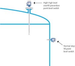
Industrial water and wastewater facilities use a variety of treatment chemicals, some of which are potentially hazardous to facility personnel and the environment. Acids, both hydrochloric and hydrofluoric, are common in wastewater treatment. Caustic, peroxide and numerous other chemical types are also used, and all of these can be hazardous to both personnel and the environment. In this article, we’ll look at how point level switches can be used to prevent overfilling of chemical storage vessels, preventing these hazardous incidents from occurring (see Fig. 1).
Level Switch Selection
Point level switches preventing overflow are typically placed in a position where they should seldom or never be used. These switches are often called High High level because they are above the stop fill high level point in the vessel (see Fig. 2). These switches may go for years without ever sensing liquid level.
Because of this, it is imperative that each High High level safety switch has a means of being tested on a regular basis to ensure it will operate in the event of an actual emergency. This test must expose any potential failures and should not require raising the product level to the switch point. Raising the level up to a High High switch for test purposes can potentially cause a spill and should be avoided.
Depending on the type of point level switch being used, the only accepted method may be to remove it from the vessel for testing. There are costs in the form of downtime and personnel hours to remove the switch, perform the test, and reinstall the switch. Further, the switch could be damaged during removal and reinstallation - or it may not be reinstalled correctly. For these reasons, employing a point level switch that can be tested in-situ should be the first choice for safety applications (see Fig. 3).
Testing validates switch operation and returns it as closely as possible to the original installed condition. Conceptually, this is referred to as Probability of Failure on Demand (PFD). When a point level switch is first installed, it has a low PFD. Over time, the PFD of the switch increases. Testing the switch re-establishes the PFD to a lower number.
It’s important to note that in-situ testing may only validate a percentage of the potential failures. This is known as a Partial Proof Test (PPT). As such, the PFD recovery is dependent on the Proof Test Coverage (PTC). The PTC is based on the percentage of failures exercised by the proof test. The higher the PTC percentage, the higher the recovery and the lower the PFD.
Since the PPT recovers only a percentage of the PFD, the switch does not return to its original installed state in terms of reliability as measured by PFD. The result is that with each PPT proof test, the PFD will be a little higher, and a full proof test will eventually be required. A level switch product with a high PTC allows for a longer period of in-situ PPT.
Several point technologies are available for level indication. Because of the critical nature of these safety switches, some technologies are better suited than others.
Float Level Switch
Float switches, as the name implies, have a float that changes position due to buoyancy, thereby indicating the presence of a liquid. The float may move on a vertical shaft and trip a magnetically coupled reed switch, or may pivot on an access point to activate a mechanical internal switch. In either case, the mechanical nature of a float switch, with its moving parts that can hang up or bind, makes it a poor choice for use in safety applications.
The ability to test a float switch is also suspect. Some manufacturers provide a lift arm to physically move the float and make it change state from normal to alarm. This may not detect leaking floats, binding or heavy coatings. Some test arms are fitted with magnets that will release if the float is heavy due to leakage or coating, but this feature is not always effective. As such, the only valid way to verify float switch operation is to remove it from the vessel and test it.
Floats are best suited for simple non-critical applications and should be avoided for safety-related applications.
Ultrasonic Gap Point Level Switch
Ultrasonic gap switches are comprised of two piezoelectric crystals situated on opposite sides of a gap. One crystal is excited electrically and generates acoustic energy directed across the gap toward the second crystal. With air or gas in the gap, the energy is not strong enough to reach the second crystal. Once the gap fills with a liquid, the acoustic energy is coupled through the liquid molecules, reaches the second crystal, and completes the circuit - indicating that liquid is present. Materials that leave coatings, have suspended solids, or are aerated will block the acoustic energy and may cause improper operation.
In-situ testing of ultrasonic gap switches to validate all potential failures is not possible. Performing a valid test on an ultrasonic gap switch requires removing it from the vessel and testing it in a sample of the liquid from the vessel. Ultrasonic gap switches are best suited for general, non-critical level applications, and should not be used for safety/spill prevention applications.
Capacitance Point Level Switch
Capacitance point level switches are based on a capacitor: one plate of the capacitor is the active center rod of the sensing element; the second plate of the capacitor is the vessel wall or an added ground rod/plate. When liquid in the vessel rises, it covers the sensing element and the capacitance increases. The output of the electronic unit changes state to indicate presence of material once the capacitance exceeds a preset switch point.
Internal diagnostics monitor data such as the base capacitance. Reduction of the base capacitance would indicate a wiring failure or a sensing element that has lost mass due to damage or corrosion. Failures can result in a switch going into fault mode or activating an “alarm” contact.
Some capacitance switches incorporate in-situ testing, but the PTC percentage for a capacitance switch PPT tends to be low. The result is that the intervals between full proof tests tend to be fairly short, increasing downtime and maintenance.
Depending on the application, a capacitance point level switch may be a good choice for a safety installation.
Vibronic (Tuning Fork) Point Level Switches
Vibronic point level switches (see Fig. 4), also called tuning forks, operate by vibrating a fork at a resident frequency in its uncovered state. When process material covers the fork, it causes the frequency to shift down, indicating the presence of the liquid and changing the output of the switch.
Because they are constantly vibrating, diagnostics are possible. Changes in frequency can indicate damage or corrosion to the fork, heavy coatings, or objects jammed between the forks. The electronic unit is constantly running self-test routines to identify these and other potential faults.
Some manufacturers provide a live signal superimposed on the current signal. This live signal is constantly switching from one current to another and back. The switching current certifies that the current signal is not stuck and ensures that the current will shift when the fork changes from the uncovered to covered state.
In-situ PPTs can be performed on vibronic point level switches. The sophisticated design of these switches employs redundant circuitry along with diagnostics. These features result in an extremely high PTC percentage. Some manufacturers provide products that will not require a full proof test for as many as twelve years, greatly reducing testing cost and increasing process availability.
Using a point level switch for High High indication is recognized as a best practice and should be followed for safety overfill applications. The reliability of a point level switch with continuous live signal will exceed other technologies in demanding critical services. As always, the application will determine the best technology for these critical safety devices.
About the Author: Bill Sholette, the Northeast region level product manager for Endress+Hauser, has spent the last 36 years consulting and specifying on level measurement instrumentation. He has also published a number of white papers and articles pertaining to level measurement. Sholette received his certification in management and marketing from Villanova University.
