AEP Power Plant Employs New Chlorine Injection System
Vacuum-Driven Sodium Hypochlorite Water Treatment System Proves an Easy Retrofit at Ohio Generating Plant
A spate of new federal and state regulations regarding use of gaseous chlorine helped convince American Electric Power, operator of the Cardinal Generating Plant in Brilliant, OH, that its aging, gaseous chlorine water disinfection system had to be replaced. The utility selected a liquid sodium hypochlorite (NaOCl) system, built around a pumpless vacuum dosing technology developed by Portacel Inc. of Houston - a unit of ITT Advanced Water Treatment.
With experience as a plant chemist, Jeff Gremelspacher, AEP steam process operator, understood the relationship between chlorine disinfection and efficiency of the plant’s steam condensers. Containing thousands of small cooling tubes, condensers absorb heat from high-purity process steam as it exits a generating turbine. The steam cools and condenses back into pure, demineralized water that’s recycled through the generating process. The greater the cooling efficiency, the faster the steam is drawn through the condenser.
But “any loss of condenser vacuum means that more BTUs of fuel are needed to achieve the same output,” says Gremelspacher. “If you consider that a 0.1-in Hg loss in condenser vacuum equals about 25 BTUs, even that tiny pressure differential − a fraction of one psi − would cost us an additional $250,000 in fuel for steam generation annually.”
Enter chlorination. Because the plant’s condensers are cooled by water pumped from the Ohio River, chlorination of the river water is essential to prevent growth of microorganisms, whose sticky excretions would otherwise form layers of slime inside cooling tubes and reduce condenser efficiency.
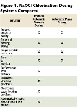
AEP’s search quickly focused on NaOCl chlorination systems because the liquid is less hazardous and easier to handle than chlorine gas and such treatment systems could be built for as little as half the cost of alternatives. There are two types of these NaOCl dispensing systems, or dosers. Both draw NaOCl solution from a storage tank, measure it precisely, and then inject it into a stream of carrier water that’s piped to the chlorination point.
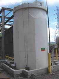
Gremelspacher decided against a pump-driven dosing system for several reasons: “A pump-driven dosing system depends on close proximity to the NaOCl storage tank. That choice would have meant placing a 6,500-gal NaOCl storage tank (about a one-month supply) inside an operating unit, causing potential spill and odor problems.”
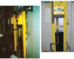
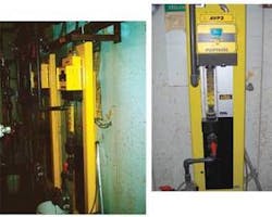
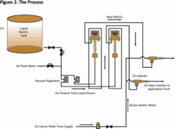
Instead, he chose two Portacel Trent automatic vacuum dosers. Slight head pressure provided by the hypo storage tank, combined with the vacuum created through the venturi effect of the inductor, pulls the NaOCl solution relatively long distances from the tank to the dosing point. A precise dose of neat NaOCl is measured by one the dosers. This dose flows directly through the inductor and mixes with the carrier water.
After working to get chlorine gas out of the facility, Gremelspacher was relieved to find that “we could put a lot of the process outside,” including the NaOCl tank, carrier water feed, and injection mixer. A single PVC pipe, carrying the dilute NaOCl and water mixture, was the only part of the new system to enter the plant. He recognized that he could dramatically reduce installation costs by connecting the incoming PVC line directly to the existing polyethylene coated pipes that carried solution from the old chlorine gas system to the inlet points for the river water. “Anybody with a chlorine gas system could probably do the same thing.”
“The beauty of the vacuum dosing system is that you’re operating under very low pressure,” Gremelspacher said. “Basically, you’ve only got head pressure from the hypo storage tank on the suction side of the injector. You’re also under vacuum, so, if a pipe breaks, the flow stops. You aren’t going to see the leakage problems you would in a pressurized system.”
