Increasing Recovery in Industrial Water Reuse
By Lior Eshed and Alex Drak
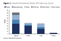
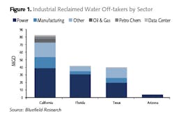
As water scarcity increases and water prices are on the rise, water reuse is becoming more common in both the municipal and industrial sectors. The leading segments in the industrial market are the heavy water users, mainly the power and energy industry (there are currently 67 power plants across the U.S. that use reclaimed water), food and beverage, the pharmaceutical industry, paper mills, and oil and gas industries (see Figure 1). Interestingly, one of the newer consumers of reclaimed water are data centers — such as Microsoft’s centers in Quincy, Wash., and San Antonio, Texas, Apple in Prineville, Ore., and other centers in the Silicon Valley — that use reclaimed water for cooling. This sector is expected to grow in the coming years.
According to Bluefield Research, the water reuse market is currently at $1.8 billion, and is expected to grow 27 percent by 2027.
The common main process scheme in water reuse includes pretreatment (such as ultrafiltration [UF]), a desalination step (reverse osmosis [RO]) and, in municipal applications, a post-treatment step of advanced oxidation, such as ultraviolet/advanced oxidation (UV/AOP), is included with the goal of removing residual organic contaminants. Some industrial applications that require very low saline content in the water, such as high-pressure boiler feed water, go through a second pass of RO.
The water is usually for internal usage but in some cases facilities that are in close proximity can partner where one facility reuses the other’s reclaimed wastewater. Other facilities, such as the Edward C. Little Water Recycling Facility in West Basin, Calif., reuses municipal wastewater effluent mostly for industrial clients in the petrochemical industry that surround the facility.
System Recovery
One of the key challenges to water reuse becoming more common is the need to increase the recovery of the system. This parameter describes the fraction of the water that is produced from the source water. Water reuse facilities usually operate at an RO recovery of about 75-85 percent, with an overall system recovery of about 67-77 percent. This is mostly important in cases when there is no easy access for brine discharge (i.e., no access to sea discharge), which makes brine discharge very expensive.
The main challenge to increasing the RO recovery is the water chemistry: as the RO recovery increases, the brine concentration rises and there is an increased risk of scaling due to precipitation of salts. Variable feed water quality may also cause similar issues.
One way to overcome these problems is to use closed-circuit reverse osmosis. Using this method, the brine is recirculated in the system to keep the required cross-flow velocity and the cycle is stopped before the layer of scaling and fouling has enough time to accumulate. However, the brine that is discharged from this process can potentially scale the pipe downstream.
A recently developed brine desalter technology, containing an RO system with an integrated salt precipitation unit, addresses these limitations, providing a solution for difficult wastewaters and successfully meeting the various challenges such as scaling by sparingly soluble salts, and organic and biofouling. The system can address varying quality feed water (1,000-70,000 mg/L TDS), and water recoveries from 25 to 99 percent. The integrated salt precipitation unit eliminates the supersaturation of sparingly soluble salts, making the brine osmotic pressure the only limiting factor.
Brine desalter test bench.
The operation principle of the brine desalter is recirculation of the treated water through the RO system at high cross-flow velocity, and continuous precipitation of supersaturated salts from the recirculated brine. This significantly reduces the concentration polarization layer near the RO membrane wall and the brine residence time in the RO membrane, and prevents precipitation of sparingly soluble salts on the membranes. The brine flows through the salt precipitation unit downstream where it reduces the saturation of sparingly soluble salts, thus enabling continuous cycles through the RO system until reaching maximal brine osmotic pressure (see Fig. 2).
Lower chemical consumption and less sludge to be discharged save operational costs, while the achievable high recovery results in significant investment savings in most applications. The savings in chemicals offsets the higher energy cost.
Brine desalter field results are promising: significant reduction (90 percent) in disposable effluent, with overall recovery of up to 97 percent of the original feed flow. This allows higher recovery of potable water from the same water source, and lower reject disposal.
The brine desalter technology can be successfully implemented in industrial applications such as mining and power industries, cooling towers, brackish water reverse osmosis plants, brine minimization, etc. The recovery of applications limited by the solubility of calcium carbonate, calcium sulfate and silica solubility can be significantly enhanced by the brine desalter technology.
In a brackish water desalination plant with high potential of calcium carbonate scaling, this technology was used to increase the recovery from 80 to 95 percent. The amount of final brine was not only reduced from 20 to 5 percent of total feed flow but also the super-saturation potential of the final brine was reduced from LSI 2.2 to 1.0–1.2, which allows the brine to be conveyed to the discharge point without the risk of scaling. The super-saturation reduction was achieved by precipitation of calcium carbonate in the salt precipitation unit.
In another application, the brine desalter successfully increased the recovery of an industrial RO plant with a high potential of silica scaling. The recovery was increased from 90 to 97 percent. Silica and calcium carbonate were precipitated in the salt precipitation unit, keeping the scaling potential of these two salts below the maximum ability of antiscalant.
Case Study: Cooling Tower Blowdown Treatment Plant
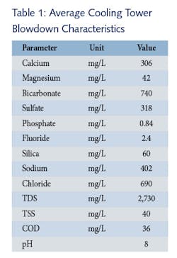
The aim of this cooling tower blowdown treatment project was to reduce the discharge from the cooling tower to zero. An additional challenge was the fact that the cooling tower uses the effluent of a wastewater treatment plant as makeup. The blowdown is characterized by a high concentration of silica, bicarbonate, calcium and organic matter, as can be seen in Table 1.
The scheme initially proposed was to remove hardness to very low values using lime softening, followed by an ion exchanger and then concentration of the effluent by RO operated at an elevated pH to prevent silica scaling and organic matter fouling. This would be followed by an evaporator and final brine elimination by a crystallizer. This strategy, however, consumes high quantities of chemicals, especially in the hardness removal step: 3,200 kg/day of lime, 2,300 kg/day of soda ash, 800 kg/day of sodium chloride, 200 kg/day of 32 percent hydrochloric acid and 100 kg/day of 50 percent sodium hydroxide.
An alternative solution for this treatment is the implementation of the recently developed RO system with an integrated salt precipitation unit. The system is designed to operate at a moderate pH level and to remove two ions from the RO brine — calcium and silica. This is done in a single-stage salt precipitation unit by precipitation of calcium carbonate together with calcium silicate. Due to the lack of calcium ions, an amount of 1,700 kg/day of lime is added continuously to the RO brine. As can be seen, the savings in chemicals are significant: the lime consumption is reduced from 3,200 to 1,700 kg/day, while the use of soda ash is eliminated.
The system is designed for 40 percent instantaneous RO recovery and maximum brine pressure of 75 bar, which corresponds to a total recovery of 97.5 percent. A five-stage configuration, with multiple inter-stage pumps, is required to design the conventional RO system for such high recovery.
The instantaneous recovery of 40 percent is achieved by a single-stage design with a good flux balance between elements (18.3 L/m2 hr average flux, 19.2 L/m2 hr lead element flux and 17.2 L/m2 hr last element flux), and high cross-flow and concentrate velocities (11.0 m3/hr feed flow per pressure vessel and 6.6 m3/hr concentrate flow rate per pressure vessel). As previously mentioned, this design prevents organic fouling and biofouling, thus minimizing the frequency of the required RO cleanings and extending the lifetime of RO membranes.
Due to the small quantity of remaining RO brine, the design is to treat this directly with a crystallizer. Even though the crystallizer of the alternative solution has higher capacity, the overall investment cost of the alternative solution is significantly lower due to the savings in the evaporator, which is not required for this solution. The savings in investment costs are between 35 and 40 percent.
Although the energy consumption of the RO section of the alternative solution is higher compared to the RO section of the initial solution, 2.2 kW hr/m³ feed compared to 1.25 kW hr/m³ feed, the overall energy consumption of the alternative solution is significantly lower, 3.4 kW/m³ feed compared to 5.7 kW/m³ feed (40 percent savings).
The savings in sludge discharge cost are also significant. The quantity of crystals discharged from the salt precipitation unit is 4,400 kg/day compared to 15,000 kg/day of sludge produced by the lime softener of the initial design.
Therefore, the alternative solution is preferable due to the savings in operational expenditures, as well as the lower investment cost. IWW
About the Authors: Lior Eshed is a product manager at IDE Technologies and leads the water reuse process team. As a process engineer, he has expertise in the field of membrane technology and has a broad range of knowledge of technologies such as membrane bioreactors, sludge treatment, log removal and more. Alex Drak has been with IDE Technologies since 2013 as an expert in industrial water treatment in the process department. He has led the process engineering teams in several projects in thermal and membrane technologies, as well as industrial water treatment projects.


