Variable frequency drives (VFDs) have been around for more than 20 years. Their reliability has increased, while their physical size has decreased. Pumps utilized with a VFD allow an induction motor to reduce speed thus flow and pressure. Before VFDs were introduced, the only way to decrease pump flow was to use a valve or stage multiple pump motors to maintain the required pressure or flow. Many are not aware of the decline of penalties charged by the utility as a result of adding VFDs to motors.
In residential, commercial and industrial arenas, the utility always has and always will bill users for the consumption of electricity. Two other less known charges are demand surcharges and power factor penalties. Both arise primarily from electrical motor usage. This article will describe both penalties and how VFDs reduced these extra surcharges.
Let’s begin with a 100 horsepower (HP) motor nameplate in Table 1.
| Model No. | NPQC100 | Serial No. | 3637717 |
| HP/kW | 100/75 | Amps | 240/120A |
| RPM | 1785 | Volts | 230/460V |
| Phase | 3 | Duty | Continuous |
| Power factor | 87 | Nom-Eff | 95.4 |
| Motor weight | 1400 lbs | Code | G |
Table 1.
Key takeaways:
HP = 100, kW = 75
Power Factor = .87 lag
Rated amps = 120 amps
(These values are at full load.)
Let’s look at charges on a bill starting with consumption charges. Consumption charges are based on kilowatt (kW) usage. KWh is kilowatts times hours. Notice the above motor is rated for 100 HP/75 kW. If this motor ran for 10 hours at 75 kW, we have 750 kWh.
Secondly, demand charges are based on kW demanded. In other words, demand is the kW used at any given time, not over a time period like consumption. Utilities look at 15-minute windows to determine the maximum average usage during that time, and the largest 15-minute time frame of use will be an added fee to the bill charged over the entire 30-day billing cycle.
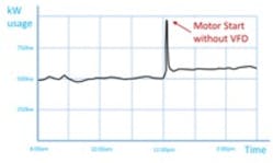
Figure 1a. Motor starting across the line
For example, suppose the normal power usage in a water treatment facility is around 500 kW, which is equivalent to about a 700 HP motor load. Suppose an additional 100 HP/75 kW motor is started across the line multiple times throughout the day to support additional needs. The consumption will move up an additional 75 kW to 575 kW (see Figure 1a). The rule of thumb for starting across the line motors is about six times the normal kW rating, so in this case, the instantaneous demand is six times 75kW or 450kW for this motor alone. Add this to the 500 kW, and we have almost 1,000 kW, which is double that of the of the original 500 kW load. So, the utility at any given time must be able to send 1,000 kW to what is normally a 500 to 600 kW need. (Fortunately, this peak load is averaged over 15 minutes.) In doing so, their cables, transformers and fusing must be sized accordingly, and they charge a demand fee. This brings a new meaning to supply and demand.
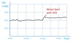
Figure 1b. Motor starting with VFD
This inrush can be reduced by adding a VFD. VFDs will never have an inrush of current. Let’s think of the VFD for a moment as an adjustable transformer that takes in fixed voltage and converts it to variable voltage. VFDs are very efficient with few losses, so let’s also assume watts in equal watts out. That means if we operate the motor at full load at 10 percent voltage, we have 46 volts at 120 amps. The input must be the inverse: 460 volts/12 amps. That means that the line input cannot see an inrush. Now, for all the engineers out there throwing up flags, it is not this linear because we didn’t take into account the inductive characteristic of the motor plays a role as well, and we would have some reactive power. However, we are not concerned with getting down to decimal places; we are looking to see the effect of the amperage on the system going from 120 amps times six, 720 amps down to an acceptable level. In this case that is down from 720 amps to the tens of amps. I’ll take the tradeoff. (See Figure 1b.)
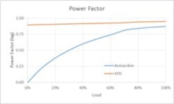
Figure 2. Power factor of across the line motor and VFD
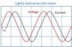
As mentioned above, motors have some inductance in them. Recall that inductance is lagging power factor and capacitance is leading power factor. Pure resistance is unity power factor. As motors are unloaded, the amount of inductance to resistance ratio increases, causing a lagging power factor. The displacement power factor is essentially the amount of lag between the voltage and current (see Figure 3a). For the most part, with loads 75 to 100 percent, the resistance dominates, and the inductance is low. Power factors at 0.87 lag or higher would be seen. Now, let’s start lowering that load to 50 percent. In Figure 2 below we see a tremendous fall off down to 0.64. Since the utility must provide this extra reactive power, it will add a penalty to the consumption charges, known as power factor penalty.
Figure 3a. Lightly loaded across the line motor
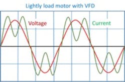
Let’s upgrade the motor by adding a VFD in front and see what happens. As the motor is lightly loaded, the diodes of the drive still conduct at the same point in time, which keeps the current and voltage in sync with no lag or nearly in sync with each other as shown in Figure 3b. This is why VFDs have a near unity displacement power factor, once again avoiding power factor penalties.
Figure 3b. Lightly loaded VFD
VFDs continue to be installed in pumping systems as their ability to change voltage and frequency to an induction motor is simplified. Their reliability, small physical sizes and networking ability make them a perfect fit for mass pump connectivity. One note of caution as seen by the VFD waveforms is that VFDs do not draw linear current from the utility and can be harmonic-rich. We will save that scenario for a future article.
Jeffery Lovelace, P.E. is the principal engineer for National Power Quality and Consulting LLC in Richmond, Texas, and has 20 years of experience with VFDs, automation systems and power quality analysis. He has a BS degree in electrical engineering from Mississippi State University and is a registered professional engineer recognized and licensed by the state of Arkansas. He is a senior member of Institute of Electrical and Electronics Engineers and an active member of the National Society of Professional Engineers. Lovelace can be reached at [email protected].

