Recovering Filter Backwash to Reduce Groundwater Consumption
In line with Saudi Aramco’s objective of reducing groundwater consumption, a ceramic membrane filtration (CMF) technology was pilot tested to treat and reuse the multimedia filters (MMF) backwash stream at a Saudi Aramco facility. This facility generates approximately 24.6 million gallons per year (MMGY) of MMF backwash stream during normal operations, which is currently considered as a waste stream and is being disposed into the facility’s sewer system. The CMF pilot unit was deployed with a flow capacity of 22 gallons per minute (GPM) for a duration of six months, during which the performance of the CMF unit was evaluated based on the removal efficiency of the five (5) micron (µm) suspended solids from the MMF backwash stream. The performance showed a high level of consistency with an average of 98 percent for the 5 µm particles despite the frequent fluctuation in feed quality and a minimum of 85 percent recovery of the backwash stream. The results also suggested that the CMF effluent water may be directly reused as a supplement to the RO system feed water, which would result in reducing groundwater demand.
Introduction
The filtration of groundwater through a multimedia filtration system is a critical step in extending the life of the 5 µm cartridge filters ahead of the reverse osmosis (RO) system. Conducting a quick evaluation and analysis on the quality of the multimedia filter backwash stream at the selected Saudi Aramco facility showed that it is an easy-to-treat stream, of which a significant portion can potentially be recovered for reuse. This is in line with the Saudi Aramco's Water Conservation Policy to reduce groundwater consumption. Consequently, the involved parties established communication to explore and evaluate potential technologies to treat and reuse this valuable wastewater stream.
The decision was made to pilot test the CMF technology to evaluate its effectiveness and efficiency in treating wastewater streams with relatively high total suspended solid (TSS), and confirm the high removal of the 5 µm particles. This marks the first time this technology has been tested in the Kingdom of Saudi Arabia and the Gulf region. The CMF technology has been applied in international locations and claimed to produce effluent quality with TSS of 1 mg/L (PPM) or less.
As previously noted, the selected facility generates approximately 24.6 MMGY of MMF backwash wastewater that is mainly mixed with other wastewater streams, and discharged into the plants’ sewer system. Thus the success of the CMF technology will contribute to the Saudi Aramco's efforts in maximizing wastewater reuse, reducing the pressure on the limited supply of natural water, and ensuring the availability of groundwater resources for future generations.
The following outlines the overarching methodology of the pilot project.
Facility Filters Operations
The MMF contain layers of sand, anthracite, and aggregate (gravel) to trap suspended and colloidal solids. The purpose is to ensure that the filtered water meets the desired Silt Density Index (SDI) of less than 3. During the operation of the filter, the captured solids build up creating a back pressure (ΔP) affecting the flow. Then the filters are backwashed periodically to remove the captured solids. As part of the operation of the filter, the degree of the filtration bed fouling is determined by monitoring and recording the SDI and ΔP data.
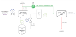
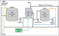
The backwash process can be initiated either manually through the respective start/stop switches or automatically based on elapsed time (7 days), SDI or ΔP across the filtration bed. The average backwash rate is 60 GPM for a 25-minute duration. As depicted in Figure 1, a side stream from the multimedia filter effluent is collected into the backwash tank (T-1), and is used for backwashing the multimedia filter. The water level in T-1 is controlled by LCV-155 level sensor. During backwash, the water flow from T-1 is pumped to the multimedia filters utilizing pumps (G-1A or B). The backwash waste (~60 GPM) is sent to a three-phase separation plant for further processing and disposal into the plant sewer system. It is the ultimate outcome of this pilot testing is to be able to recover the MMF backwash and directly supplement the RO system feed stream (shown in green), which will save about 20 MMGY of groundwater.
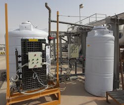
Ceramic Membrane Filtration Pilot Unit
Ceramic materials exhibit attractive properties, including: extremely low thermal expansion, low thermal conductivity, excellent elastic and good thermal shock characteristics, low dielectric losses, imperviousness to ultraviolet rays, chemical purity, corrosion resistance, and high resistance to acidic water. The CMF unit consists of the following:
· Eight cassettes:
o One cover housing cassette
o One dummy housing cassette
o Five flat sheet ceramic membrane cassettes
o One bottom air scouring cassette
· Control PLC panel for automatic operations
· Permeate pump and tank
· Feed pump and tank
· Valves, piping, and instrumentation
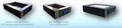
The Filter Cassettes Stack
The stack of five cassettes provides an effluent flow rate of 4.5 GPM per cassette for a total flow of 22 GPM filtration capacity. Figure 2 shows the CMF unit cassettes. A dummy cassette is positioned at the bottom. This cassette also houses the scour air disperser for extending the filtration operation of the unit between backwashing, and for aiding in the floatation action of the removed suspended solids by carrying them out of the unit through the reject line. Above the dummy cassette sits the CMF unit’s feed cassette. This enables the incoming feed to travel up the five ceramic membrane cassettes stack. The top cassette has a 3-inch effluent nozzle, which is connected to an overhead static (1-meter-high) piping system, ensuring constant head for optimum membrane operation.
The ceramic membrane housings are designed to work under 2 bar pressure. They are stacked and bolted down with proper gaskets to ensure a sealed system. Each individual cassette has its own 1-inch effluent connection and is attached to a 2-inch common header. The MMF backwash feed enters via the bottom two cassettes. Scouring air is provided also at the bottom cassettes. The ceramic membranes are placed in such a way to allow uniform scouring throughout the entire system. Manual isolating valves are provided for offline maintenance purposes. This setup of the cassettes comprises the CMF stack. For larger systems containing multiple stacks, the design allows easy removal of an individual stack for repair or maintenance.
Piping, Valves and Instrumentation
The piping material utilized in the manufacturing of the CMF stack is PVC. Sampling points for the feed and effluent are provided. The automatic valves are SS-316 and controlled with the PLC while the manual valves are CPVC.

As Figure 3 illustrates, the unit’s instrumentation includes:
· PLC operation
· Automatic operation of pumps and scour air supply
· Stack level controls
· Chorine injection operation
· Feed, effluent and return discharge pressure monitoring
· Return pump discharge pressure monitoring
Design Parameters and Process Flow Diagram
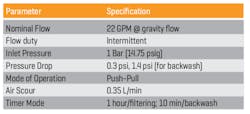
The operational conditions of the CMF pilot unit are presented in Table 1.
The particles are carried over to the top cassette where the reject line is located. The particles rise by the flow movement and the rising scouring air. This process prevents the removed solid particles from building up on the membrane. The reject is about 10 percent of feed flow rate (leaving 90 percent of feed flow to pass through the flat sheet ceramic membranes) and exits through the CMF unit’s effluent line. Solid particles above 5 µm are filtered and returned and discharged through the reject line (see Fig. 4). An indication of membrane breakage is the excessive effluent particles. This is most likely caused by vibration or overpressure. However, an indication of the need to backwash the CMF is the high transmembrane pressure and/or reduced effluent flow rate.
During the CMF unit backwash routine, the CMF PLC stops the MMF backwash feed pump and turns on the CMF backwash water pump and automatic valve. The requirement for the backwash water is a particle content of less than 5 µm and a chlorine level of about 10 parts per million (PPM). This CMF pilot unit design has been modified for intermittent operation. The PLC will prevent activating the CMF system if the feed tank is not completely full. The CMF operates for a duration of 1.0 to 1.5 hours, followed by a 10-minute duration of backwash.
The CMF unit requires limited operator attendance such as ensuring chemical inventory for CMF backwash operation, samples collection, and analysis of particle size distribution (PSD), as well as recording of flow rates and feed pressure.
Results and Discussion
The CMF unit was started on July 8, 2019. Preliminary results were collected for fine-tuning the CMF unit operations. The collected data consisted of particle count/distribution of samples before and after the CMF unit. Due to a few challenges, including the relocation of the discharge outlet to the open sump nearby and the total shutdown after the incident on September 14, 2019, the CMF unit had to be stopped, and a second start date was established on December 11, 2019. The pilot test was concluded on February 13, 2020.
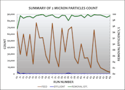
The results of the preliminary testing collected during the setup and commissioning period show encouraging removal of suspended solids larger than 5 µm, which favor the consideration of directly feeding the CMF unit effluent as a supplement to the RO system feed water line. Additional particle size distributions were measured by the PSD analyzer, and they include 2 µm and 10 µm particles. The removal efficiency of suspended particles during the preliminary testing ranged between 92.5 and 99 percent. Although the CMF unit effluent quality at this stage meets RO specifications, additional testing was required to ensure the efficiency and reliability of the CMF unit.
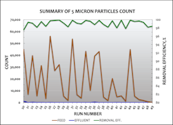
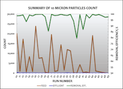
After fine-tuning the CMF unit, addressing all challenges, and reaching acceptable operating conditions, real testing started. Over the duration of the testing, a total of 30 samples were collected for particle size distribution analysis. Figures 5, 6, and 7 illustrate the 2, 5, and 10 µm size distributions. The collected samples consisted of the CMF feed (brown line) and the CMF unit effluent (blue line). Accordingly, the suspended particle removal efficiency showed a very high level of consistency, with an average of 98 percent for the 5 µm particles despite the frequent fluctuation in feed quality. According to these results, the effluent quality at this specification may be directly mixed with the RO system feed line.
Inspection of the CMF Unit
Upon the completion of the study, all eight cassettes were dismantled and inspected in sequence from top to bottom. As expected, the bottom cassettes were the most stained because the CMF unit is fed from the bottom. The membranes were in good condition and the channels were clear. Furthermore, large particles were found on the bottom cassette and white precipitates on the air distributor pores were observed. The CMF unit components were cleaned with chemicals and disinfected with a hypochlorite solution. After cleaning, the unit was reassembled and ready for use.
Conclusion and Recommendations
In conclusion, this pilot test proved the technical merit of the ceramic membrane filtration technology in effectively treating and removing suspended solids from the multimedia filter backwash stream. The quality of the CMF unit effluent remained consistent at above 98 percent removal efficiency, despite the fluctuations of the feed suspended solids level. Furthermore, the quality of the CMF unit effluent met the requirement for the RO system feed water, and hence may be directly fed to supplement the RO water demand.
The facility generates approximately 24.6 million gallons per year of MMF backwash wastewater that is discharged to the environment. The pilot study results indicated that the CMF technology will allow recovery of between 85 and 90 percent of MMF backwash wastewater, for a total of about 22 million gallons of groundwater per year. The significance of this pilot study lies in its contribution to maximizing Saudi Aramco's efforts in wastewater reuse. Other applications for testing should also be considered, including: treating and recovering other process wastewater streams, filtering seawater, and cooling systems blowdown streams. It is also recommended to test the CMF technology at other facilities with large RO plants. WT
Acknowledgment
The authors would like to thank EPD management, especially Mohammad Sahli and Thamer Al-Mutairi, for their guidance and technical input throughout this study. Appreciation is extended to APOD management, especially Nasser J Alshahrani and Abdulaziz Al-Subaie, for their efforts to expedite the installation, start-up and the completion of this collaborative project. In addition, the authors would like to extend their gratitude to Mohsen Al-Otaibi of Linear Saudi Co LTD for his on-site presence and support.
Nidal Samad, a QEP and IRCA Certified Lead Auditor ISO 14001:2015, is an environmental specialist and holds degrees in Chemistry, Chemical Engineering and Environmental Science. He has 24 patents and more than 29 years of experience in water and wastewater treatment. From 2015-2017, he held the position of Vice President at Saudi Arabian Water Environment Association (SAWEA), the official local chapter of the USA Water Environment Federation (WEF). Sohaib Alhajhussein and Mohammad Badruzzaman are both with Saudi Aramco's Environmental Protection Department (Dhahran, Saudi Arabia). Mohammed Mugahwi is with Saudi Aramco's Abqaiq Plants Operations Department (Abqaiq, Saudi Arabia). Leow Teng Hee is with Linear Saudi Co LTD (Saudi Arabia).
References
1. Hamad, J.Z., C. Ha, M.D. Kennedy, and G.L. Amy. “Application of ceramic membranes for seawater reverse osmosis (SWRO) pre-treatment,” Journal of Desalination and Water Treatment, Vol. 51, 2013.
2. Amin, Sh. K., H.A.M. Abdallah, M.H. Roushdy, and S.A. El-Sherbiny, “An Overview of Production and Development of Ceramic Membranes,” International Journal of Applied Engineering Research, Vol. 11, 2016.
3. De Angelisa, Laura, and María Marta Fidalgode Cortalezzia, "Ceramic membrane filtration of organic compounds: Effect of concentration, pH, and mixtures interactions on fouling,” Separation and Purification Technology, Vol. 118, 2013.
4. Saudi Aramco, Water Conservation Policy, 2011.
About the Author

Nidal Samad
Nidal Samad, a QEP and IRCA Certified Lead Auditor ISO 14001:2015, is an environmental specialist and holds degrees in chemistry, chemical engineering and environmental science. He has 24 patents and more than 29 years of experience in water and wastewater treatment. From 2015-2017, he held the position of vice president at Saudi Arabian Water Environment Association (SAWEA), the official local chapter of the USA Water Environment Federation (WEF).
Sohaib Alhajhussein
Sohaib Alhajhussein is with Saudi Aramco's Environmental Protection Department (Dhahran, Saudi Arabia).
Mohammad Badruzzaman
Mohammad Badruzzaman is with Saudi Aramco's Environmental Protection Department (Dhahran, Saudi Arabia).
Mohammed Mugahwi
Mohammed Mugahwi is with Saudi Aramco's Abqaiq Plants Operations Department (Abqaiq, Saudi Arabia).
Teng Hee Leow
Leow Teng Hee is with Linear Saudi Co LTD (Saudi Arabia).