Pump Issues: Understanding Sealless Pump Systems and Applications
By Kenneth Comerford
Editor’s note: This is the first in a two part series examining sealless pump technologies
Heightened awareness of environmental, safety and maintenance issues in recent years has made process-fluid leakage a paramount concern in chemical processing plants and municipal wastewater facilities. The ability of sealless pumps to prevent or minimize leakage has made them the often-preferred choice for pumping of acidic, caustic and abrasive solutions that cause seals to fail, as well as toxic solutions that require absolute containment. After years of being considered niche products for specialty applications, sealless pumps have become mainstream.
Pump design trends with respect to the handling of corrosive and abrasive fluids point to the use of sealless configurations to minimize leakage, and the specification of nonmetallic, chemically inert, and abrasion-resistant materials of construction to ensure resistance to acids, caustics, salts and other aggressive fluids. To select the optimum sealless pump for an application, one must become familiar with the technical and economic issues involved in the pump-selection process, the available pump types, and the various nonmetallic materials that are suitable for the service.
Defining a Sealless Pump
The Hydraulic Institute (Parsippany, NJ) defines a sealless pump as one in which the impeller shaft is completely contained in a sealed, pressurized vessel (called the containment shell) that contains the process fluid. Leakage of the pump fluid into the surrounding environment is prevented by the exclusive use of static, rather than dynamic, sealing technology. Only two pump designs meet this definition: the magnetic-drive pump (MDP), in which the impeller shaft is driven by a magnetic-coupling arrangement, and the canned-motor pump (CMP), which features a rotating magnetic field within the motor stator. The Hydraulic Institute definition is therefore valid, but limiting.
For the purpose of this article, a sealless pump is defined as one that does not use packing or mechanical seals to isolate the process fluid. This broader definition permits consideration of a larger group of pump designs. There is, however, no intent to imply that these other sealless-pump designs eliminate the risk of hazardous or toxic emissions.
This discussion is based on a search of commercially available designs with a focus on ones whose fluid-contacting parts are made of nonmetallic materials. No implication is made that this search has been all-inclusive and that all commercial products have been reviewed.
A wide variety of nonmetallic materials is available for the construction of wetted pump components used in corrosive-fluid applications. These include thermoplastics, thermosets and elastomers. A general knowledge of the characteristics of each class of material is helpful in selecting the proper one for a particular application.
Sealless pump types
If the elimination of the mechanical seal is an important factor in pump selection, then there are other pump types, in addition to the MDP and CMP, that deserve consideration. But the choices narrow as application and service requirements become more stringent.
For instance, if the pump must be chemically resistant to the process fluid, the scope becomes limited to units with wetted components made of the stainless steels, high and exotic alloys and nonmetallics. If the analysis is restricted to applications where non-metallic materials are considered ideal for providing the required chemical resistance, then the options are limited to five commonly used sealless pumps whose wetted parts are made of thermoplastic, thermoset and elastomeric materials. These configurations are the magnetic-drive pump, the coupled wet-pit vertical sump pump, the flexible-tube pump, the flexible-liner pump and the controlled-volume diaphragm pump.
The next segment of this article briefly describes the design principles of each of these nonmetallic pump configurations.
Magnetic drive pump
The magnetic-drive centrifugal pump offers flows to approximately 1,000 gal/min, and heads up to 350 ft. A nonmetallic containment shell or can encloses and statically seals the entire impeller-rotor assembly, as well as the pumped fluid. This pump has two shafts. The driven shaft is located in the liquid end of the pump and is supported by sleeve bearings. The impeller and the inner magnet are mounted on this shaft. The other shaft, called the driving shaft, is either a close-coupled motor shaft or one that is supported by antifriction bearings in the pump-bearing housing. The driving magnet surrounds the containment shell and is mounted on this shaft.
Coupled, vertical sump pump
The coupled, wet-pit vertical sump pump discussed here is a non-metallic sump pump that does not employ shaft-sealing arrangements. It offers flow rates up to 4,000 gal/min and heads up to 350 ft., and can be used in sumps as deep as 50 ft.
In this class of pumps, the impeller’s hydraulic design is of a radial type, and the pumped fluid exits through a separate discharge pipe rather then coming up through the column. The pumped fluid that fills the column is returned to the sump through radial leakage holes in the column. The pressure in the column is atmospheric at the uppermost leakage hole situated below the manhole cover, so that the liquid level in the column remains below the point at which the shaft penetrates the pump support plate – hence a shaft liquid seal is not required. A dynamic vapor seal is employed in many cases, at the juncture between the shaft and cover plate to prevent escape of corrosive fumes that might attack the motor and its support bracket. The open-line shaft bearings are typically product-lubricated.
Vertical pumps are furnished in a variety of configurations, including cantilevered-shaft designs, which are suitable for dry-running conditions; vortex-recessed impeller designs, for handling fluids with solids or stringy debris; and segmented-shaft designs, for installation in extremely deep sumps, or for installations of tall pumps in low-headroom areas.
Flexible-tube pump
The flexible-tube pump does not use mechanical seals. Instead, the fluid is contained within the smooth walls of an elastomeric, tubular structure and is moved forward as the tube is squeezed by a rotating element. As the squeezed tube returns to it natural shape, the vacuum produced by the displaced fluid draws more fluid into the tube. Pumping is achieved by a gentle, peristaltic action that allows for a controllable flow of the fluid trapped between the two contact points on the inside of the tube. This configuration requires no seals, glands or valves. Models are available with flow rates up to 200 gal/min and differential pressures to 200 psi.
Flexible-liner pump
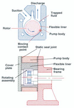
The flexible-liner pump moves the fluid forward peristaltically via an eccentrically mounted rotor that applies pressure from the inside of a flexible liner within the pump body. Fluid is contained within a channel-like cavity formed by the outer surface of this elastomeric liner and the inner surface of the thermoplastic pump body. The rotor is mounted on an eccentric shaft that oscillates within the liner and progressively moves the sealing contact point between the liner and pump body, effecting a squeegee action on the trapped fluid.
The flexible-liner pump is available in either close-coupled or pedestal-mounted configurations. It is self-priming and has no stuffing boxes, glands, valves or gaskets. Flow rates range from 0.30 to 40 gal/min, with a maximum differential pressure of 30 psi. The pump can be driven by an electric, gasoline or air motor.
Diaphragm pump
The controlled-volume diaphragm pump has a flexible diaphragm that directly contacts the process fluid. This diaphragm also acts as a seal between the drive mechanism and the pumped liquid.
Many design configurations are available. The diaphragm can be driven mechanically, hydraulically, pneumatically or electromagnetically. The pumps are available in single-, double- and multiple-diaphragm configurations. All diaphragm pumps are sealless and self-priming, and can be run dry without causing damage. Flow rates of 200 gal/min and outlet pressures of 100 psig are common.
About the Author: Ken Comerford is Vice President, Vanton Pump and Equipment Corp. Since joining the company in 1982, he has served in a variety of roles including Sales and Marketing Manager. He was promoted to Vice President in 2006, and currently sits on the board of directors and is a member of the Water Environment Association.


